Quick Start
Copyright © ITECH Electronic Co., Ltd. 20
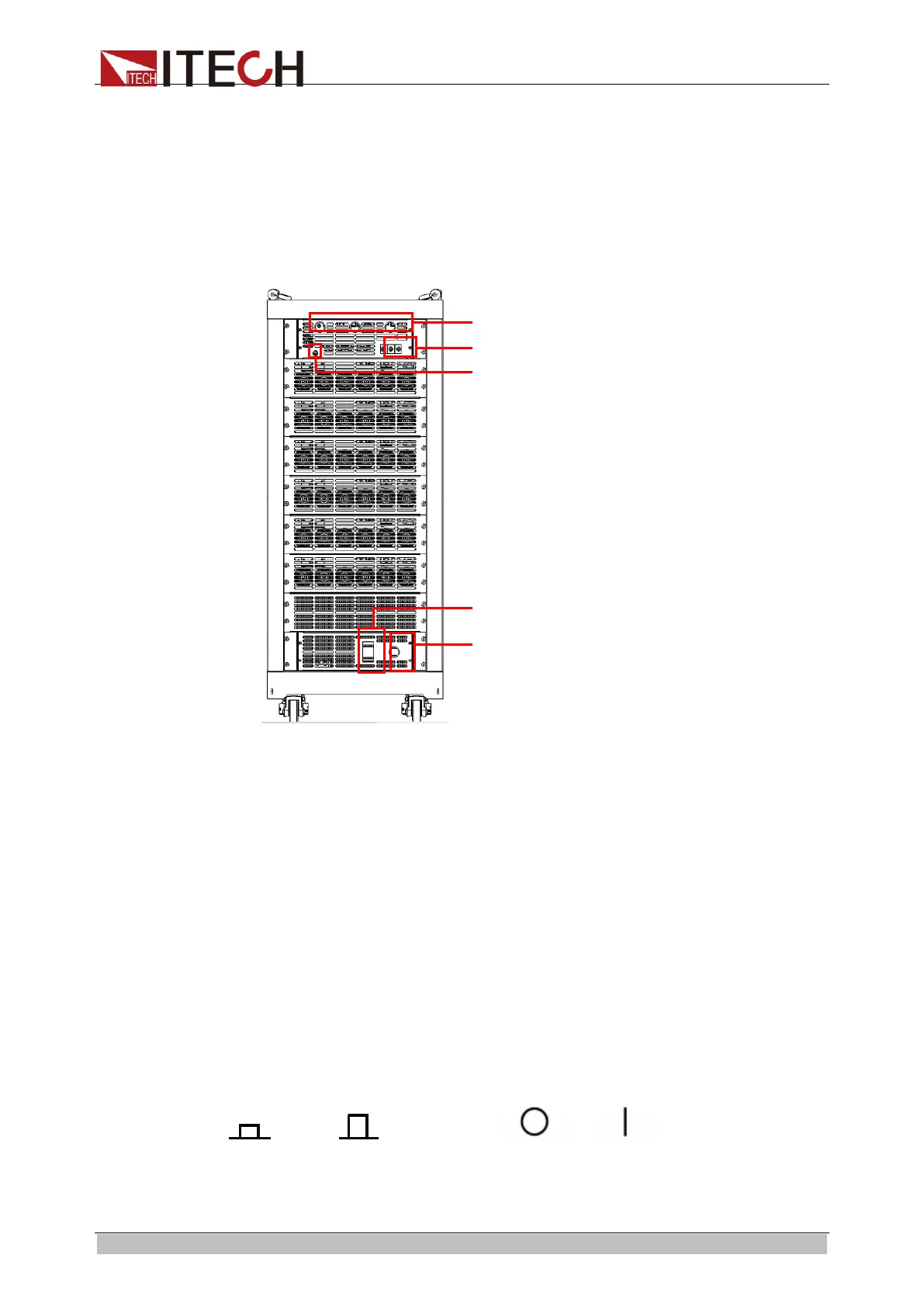
⚫ The rear panel of IT8624/IT8625/IT8626/IT8627/IT8628 is shown in the
next figure. (Take the example of IT8625).
Before connecting the communication terminals, you need to take apart the
rear panel which covers the communication terminals by using a
screwdriver. IT8620 series electronic loads have two groups of system bus
interfaces. One of them is used to connect the internal instruments which
make up the cabinet, which is connected well when delivered; the other is
used to connect between the cabinets to realize the parallel or three-phase
function. Other communication terminals are the same as those of IT8615.
1. Communication interface threading hole
2. Load input terminal threading hole
3. Remote measurement terminal threading hole
4. Power master switch
5. AC power cord threading hole
2.7 Power-on Self-test
A successful self-test indicates that the purchased product meets delivery
standards and is available for normal usage. Before operation, please confirm
that you have fully understood the safety instructions.
Introduction of Switch
You can turn on the instrument by switch. Descriptions of the switch are as
follows:
ООО "Техэнком" Контрольно-измерительные приборы и оборудование www.tehencom.com

 Loading...