en 64
8 ADJUSTMENTS
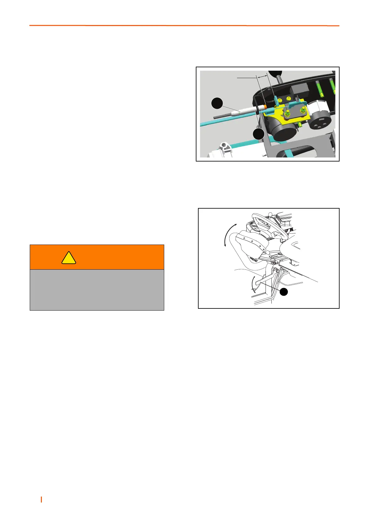
8.2 ADJUSTING SPEED CONTROL SWITCH __________________________________
The speed control sensor is positioned under the control
panel. The mechanism is activated when the speed control
lever is cycled from the transport and mow positions.
To set the sensor (A), position the control lever in the “mow”
position, loosen nuts (B), and adjust sensor until a gap of
4mm is achieved. Tighten nuts. Cycle control lever to the
“transport” position, to ensure bolt head is clear of switch.
To ensure correct set-up, the cylinders MUST only rotate
when the switch is activated. i.e the Mow position.
8.3 STEERING ARM ADJUSTMENT _________________________________________
Support the control arm to avoid a sudden drop while adjusting its height. Loosen the Locking Lever (A) to allow
the steering wheel and control arm to be adjusted up or down. Tighten the locking lever when steering wheel is at
the desired position.
WARNING
DO NOT attempt to adjust the control arm
position while the machine is moving.
The operator may loose control, causing
possible injury to themselves or bystanders.
!
A
 Loading...