Basic System Operation
Joystick Controllers - Description
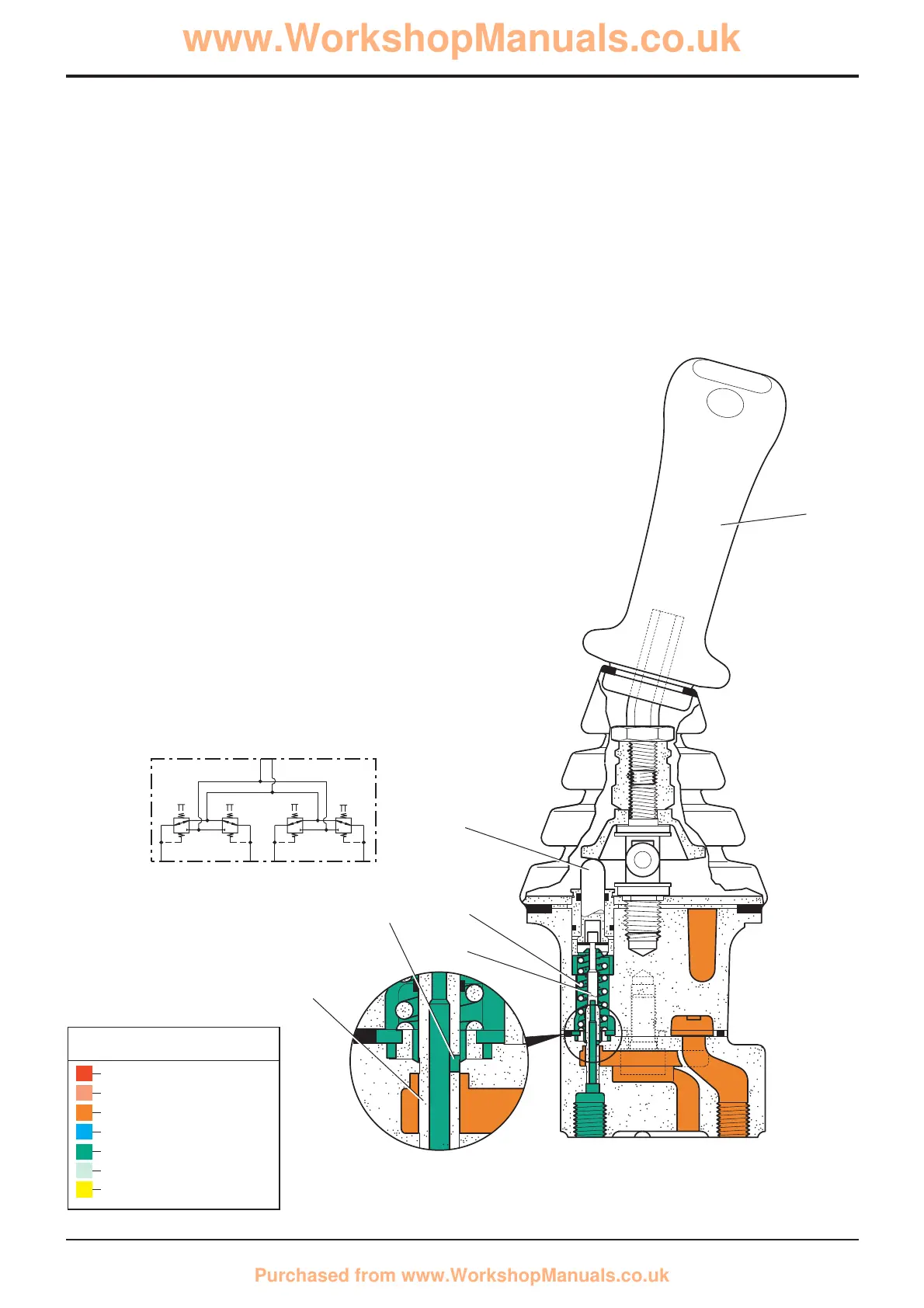
The joystick controllers operate as direct operated pressure
reducing valves and consist of a hand control lever, four
pressure reducing valves and the housing. Each pressure
reducing valve consists of a control spool, control spring,
return spring and a plunger.
In neutral the control lever 5 is kept in the central position by
the return spring 8. Service ports 1, 2, 3 and 4 are connected
to the tank port T via gallery 11.
When the control lever 5 is operated, plunger 9 pushes
against return spring 8 and control spring 7. The control
spring 7 moves the control spool 6 down-wards and closes
the connection between the relevant service port and the
tank port T. The service port is connected to the pressure
port P via gallery 11.
The control phase begins when the control spool 6 has
found its balance between the force of the control spring 7
and the force which results from the hydraulic pressure in the
selected port.
The interaction of the control spool 6 and control spring 7
enables the plunger 9 to produce pressure proportional to
the position of the control lever 5.
 Loading...