7 - 2
Loader Valve - Variable Flow
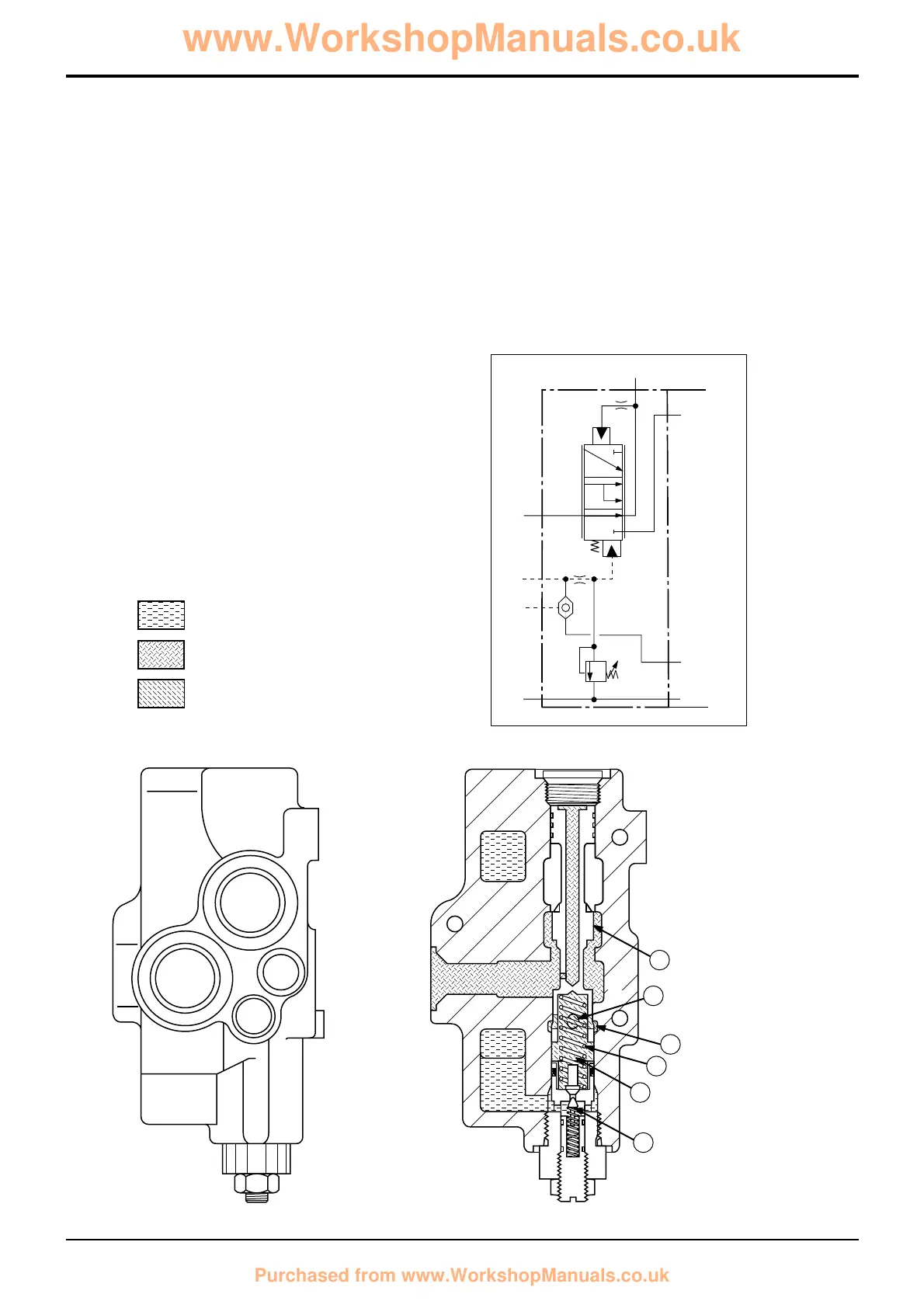
Priority Inlet Section Operation
The priority inlet section houses the steering priority valve
and a relief valve assembly. Operation is as follows:
Steering
When the steering wheel is turned, a priority pressure
demand signal is sent from the hydraulic steer unit and
received at the priority inlet section (port PRLS). The signal
oil flows through port A into chamber C via gallery B.
The combined force of spring D and signal oil pressure
moves spool E up. The position of the spool now allows oil
from the pump inlet port P to flow out to the hydraulic steer
unit via priority work port PR.
It must be noted that relief valve assembly J is redundant.
This relief valve is part of the inlet section, however the
hydraulic steer unit also houses a steer system relief valve.
To ensure the relief valve in the hydraulic steer unit controls
the steer system pressure, valve J is set abnormally high
(172 bar; 2500 lb/in
2
).
Component Key:
P Pump Inlet
T Tank
LS Load sense port (to pump)
PRLS Priority Load Sense Port (from steer unit)
PR Priority Work Port (to steer unit)
Section E
Hydraulics
9803/3280
Section E
7 - 2
Issue 1
Circuit Descriptions
 Loading...