Part No. 960-100941R_Rev. A © 2016 JCM American Corporation
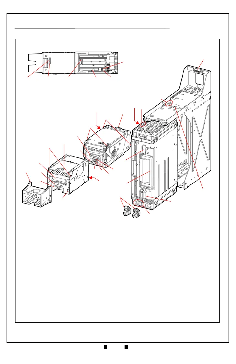
Figure 2 TBV Component Names
1. Interface Connector
2. Cash Box Lock Lever (Back Side)
3. ICB Sensor Lens Assembly (Option)
4. ICB Power Switch (DS7) (Option)
5. Transport Signal Connector
6. Transport Section Rear Guide Latch
7. Centering Release Port (Back Side)
8. Transport Section Front Guide Release Latch
9. Transport Section Release Lever
10.LED Indicator (Green/Yellow/Red)
11. Return Path Open/Close Cover
12.BNF Guide Latch
13.Pusher Plate
14.BNF LED Indicator (Full Color Range)
15.Bezel (Standard)
16.BNF/Transport Section Release Lever
17.USB Connector Port
18.BNF Connector (Back Side)
19.Transport USB Connector Port
20.Denomination INHIBIT/ACCEPT Switches
(DS3 [Set identical as DS1])
21.Bezel LED Indicator Connector
22.Transport Signal Connector
23.Cash Box Release Lever
24.Cash Box Handle
25.Thumb Twist Lock Knob
(replaced by Optional Lock)
26.Cash Box Seal Assembly (Option)
27.Cash Box Lock Lever (Back Side)
28.Denomination INHIBIT/ACCEPT Switches
(DS1 [Set identical as DS3])
29.Set BNF Buzzer Volume Switches (DS2)
30.TBV Centering Mechanism ON/OFF & Select
Communication Interface Switches (DS4)
31.ICB Sensor
32.TBV Photo-Coupler/RS232 Interface
Selection Switch (DS5)
33.TBV Option Memory Selection Switches
(DS6)
34.Lock & Key Assembly (Option)

 Loading...

