EasyManua.ls Logo

JR 10X User Manual

JR 10X
76 pages
To Next Page IconTo Next Page
To Previous Page IconTo Previous Page
Page #42 background imageLoading...
Page #42 background image
Standard Programmable Mixing
The 10X provides five standard programmable mixes.
Programmable mixes are used whenever the pilot wants a chan-
nel/servo to react or move as a result of providing input to anoth-
er channel. The channel that reacts is called the Slave channel,
while the channel that receives direct input is called the Master
channel. Under this concept, when the pilot provides an input to
the Master channel, the transmitter automatically generates an
input for the Slave channel/servo so that it moves in a specified
direction for a specified amount.
Mixes are programmable, allowing any of the 10 channels to be
Master, Slave or both. The offset (mix neutral point), direction
and travel can all be programmed and adjusted.
Accessing and Utilizing the Standard
Programmable Mixing Function
To access the Programmable Mixing function, enter the proper
code, 51-55, in the code number access selection or use the direct
mode method. The screen will appear as follows:
Each channel of your transmitter and receiver has been assigned a
number for identification purposes. Use the following chart to
identify the channel and its identification number.
The first number key you select becomes the Master channel. It
also activates the mix feature. The Master channel is the channel
from which you want to mix. In other words, this is the control-
ling channel for the mixing feature.
The second number key selected becomes the Slave channel. The
Slave channel is the channel that is being mixed into the Master
channel. You can also think of it as the controlled channel for the
mixing feature.
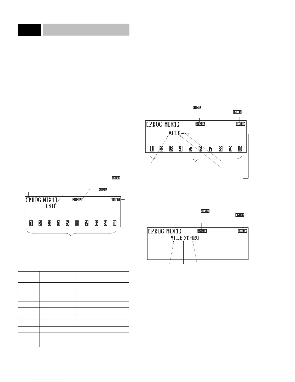
For example, you want to mix the aileron channel to the throttle
channel. Aileron is the Master, or controlling, channel. Throttle is
the Slave, or controlled, channel. The initial screen shows that the
mixing feature is inhibited. However, after aileron is selected the
screen will appear as follows:
Next, choose the Slave channel—in our example, throttle. The
screen will now change to display:
Note: Once both the Master and Slave channels have been
selected, the channel numbers are removed from the bottom of the
screen. If you have mistakenly entered a wrong channel number
for either the Master or the Slave channels, touch the CANCEL
key and reprogram the mixing channels.
42
10X MANUAL Airplane
8.13
Code 51-55
Indicates program
being accessed
Indicates that MIX 1
is currently inhibited
Touch to cancel
current mix if activated
Touch to select master
and slave channels
Touch to
exit program
Channel # Receiver Channel Complete Channel Name
1 THRO Throttle
2 AILE Aileron
3 ELEV Elevator
4 RUDD Rudder
5 GEAR Gear/Retract
6 AUX1 Auxiliary 1 (flaps)
7 AUX2 Auxiliary 2
8 AUX3 Auxiliary 3
9 AUX4 Auxiliary 4
10 AUX5 Auxiliary 5
Touch to
exit program
Indicates that MIX 1
is active and that the
master channel is
aileron
Indicates feature
being accessed
Slave channel
when selected
Indicates mix to
channel
Master channel
Touch to select master
and slave channels
Touch to cancel
current mix and return to
mix inhibited screen
Touch
to proceed to
next screen
Indicates
feature being
accessed
Indicates
that MIX 1
is active
Master
channel
Touch to
cancel current mix
and return to mix
inhibited screen
To
Slave
channel

Table of Contents

Question and Answer IconNeed help?

Do you have a question about the JR 10X and is the answer not in the manual?

JR 10X Specifications

General IconGeneral
BrandJR
Model10X
CategoryRemote Control
LanguageEnglish

Summary

10X User Manual Airplane Version

1 Features

1.1 Transmitter

Features of the transmitter, including flight modes, digital trims, and throttle trim.

1.2 Receiver

Specifications and features of the NER 950S receiver.

1.3 Digital Servos

Features and specifications of JR Digital Servos, including DS8231.

2 Component Specifications

2.1 System Specifications

Details the overall system components for the 10X.

2.2 Transmitter Specifications

Lists technical specifications for the J120FS transmitter.

2.3 Servo Specifications

Provides specifications for the NES-8231 Digital Servo.

2.4 Receiver Specifications

Details technical specifications for the NER-950S receiver.

2.5 Charger Specifications

Lists specifications for the NEC-222 charger.

2.6 Airborne Battery Packs

Details specifications for the 1400 mAh Sanyo Extra NiCad battery.

3 Transmitter Controls

3.1 Control Identification

Identifies all physical controls and switches on the transmitter.

3.2 Transmitter Rear

Details controls and ports located on the rear of the transmitter.

3.3 Control Stick Length Adjustment

Explains how to adjust the length of the control sticks.

3.4 Neck Strap Attachment

Describes how to attach a neck strap for balance.

3.5 Adjustment of Stick Tension

Guides on how to adjust the tension of the control sticks.

3.6 Direct Servo Control (DSC)

3.7 Frequency Notes/Aircraft Only Frequency

4 Connections

4.1 Installation Requirements

Offers suggestions for proper radio system installation in aircraft.

4.2 Connections

Illustrates wiring and connection diagrams for system components.

5 Display and Touch Panel

5.1 Care of the Touch Screen

Provides guidelines for cleaning and maintaining the touch screen display.

5.2 Operating the Touch Panel

Explains basic touch panel operations and key inputs.

6 Alarm & Error Display

6.1 Battery Alarm

Describes the low voltage battery alarm and its indicators.

6.2 Back-Up Error Alarm

Explains the alarm for lithium back-up battery failure.

7 Data Input

7.1 Code Number Access

Details how to access functions using code numbers.

7.1 Direct Mode Access

Explains how to access functions via direct mode selection.

8 Code Functions

8.1 Code 11 Reversing Switches

Explains how to electronically reverse servo throws for any channel.

8.2 Code 12 Travel Adjust/ATV/End Point Adjust

Guides on adjusting servo travel limits for each channel.

8.3 Code 13 Dual Rate/Exponential Adjustments

Covers programming dual rates and exponential curves for flight controls.

8.13 Standard Programmable Mixing

Explains setting up standard programmable mixes between channels.

8.1 Code 11 Reversing Switches

8.2 Code 12 Travel Adjust/ATV/End Point Adjust

8.3 Code 13 Dual Rate/Exponential Adjustments

8.4 Code 14 Trace Rate

8.5 Code 15 Sub-Trim Adjustment

8.6 Code 17 Function Select

Flight Mode Switch Position

Explains how flight modes are assigned to switch positions.

Utilizing Flight Modes

Recommends a phased approach to programming and using flight modes.

Preliminary Flight Mode Programming

Flaps

Servo Speed

Gyro Gain

Aileron Differential

Snap Rolls

Aileron-to-Rudder Mixing

Rudder-to-Aileron/Elevator Mixing

Programmable Mixing

8.7 Code 18 Programmable Throttle Curve

Switch Selection

Explains how to select throttle curves using switches or flight modes.

8.8 Code 22 Wing Type Selection

Normal Wing Type Selection

Describes the default wing type for aircraft with single aileron servo.

Flaperons

Explains using ailerons as flaps and their control setup.

Quad Flaps

Quad Flap Operation

V-Tail Mixing

V-Tail Operation

Dual Elevator Mix

8.9 Code 24 Servo Speed

8.10 Code 28 Data Reset

8.11 Code 31 Snap Roll

Pre-Programming Snap Rolls to Flight Modes

Details assigning snap roll direction and rates to flight modes.

8.12 Code 44 Gyro Gain Sensitivity System

Connections

Explains how to connect gyros to the receiver ports.

Accessing Standard Gyro Gain Sensitivity

Guides on accessing the basic gyro gain adjustment feature.

Setting the Gain Percentages

Assigning Gyro Gains to AUX2 or Flight Modes

Explains assigning gyro gains to switches or flight modes.

Accessing the Stick Priority Gyro Gain Feature

Describes the stick priority feature for gyro gain override.

8.13 Code 51-55 Standard Programmable Mixing

Accessing and Utilizing the Standard Programmable Mixing Function

Guides on setting up standard programmable mixes between channels.

Offset Operation

Mixing Value

Include Mixing

Origin Mixing

Mixing With Trim

8.14 Code 56-58 Multi-Point Programmable Mixing

Accessing and Utilizing the Multi-Point Programmable Mixing

Guides on defining custom curves for slave channel response to master channel.

Exponential Function

Practical Applications

8.15 Code 62 Aileron-to-Rudder Mixing

8.16 Code 63 Elevator-to-Flap Mixing

8.17 Code 64 Rudder-to-Aileron/Elevator Mixing

Switch Selection

Explains assigning rudder-to-aileron/elevator mixing to switches/modes.

8.18 Code 66 Flap System

Flight Mode Select

Allows programming flap/elevator positions for specific flight modes.

Auto Land

Details setting an auto land throttle position to retract flaps.

8.19 Code 75 Servo Monitor

Servo Test (Slow/Step)

Guides on testing servos for wear by cycling their travel.

8.20 Code 77 Fail-Safe/Hold

Hold (Z PCM)

Explains the Hold function which stops servos at last signal position.

Fail-Safe (Z PCM)

Details setting preset servo positions for signal loss conditions.

SPCM Hold

SPCM Fail-Safe

Combination Fail-Safe and Hold (S PCM)

8.21 Code 78 Pilot Link

Using the 10X as a Master

Explains using the 10X as the master in a buddy box setup.

8.22 Code 81 Model Name Input

8.23 Code 83 Digital Trims and Trim Rate Adjustment

Accessing and Utilizing the Trim Rate Feature

Guides on adjusting digital trim sensitivity and rate.

8.24 Code 84 Model Selection (1-10)

Model Selection

Explains how to select and navigate through model memories.

Copy Function

Details transferring model memory between transmitters or PC.

8.25 Code 85 Modulation Selection

8.26 Code 86 Data Transfer

Preparing the Transmit Radio

Guides on preparing the transmitter for data transfer.

To Access the Data Transfer Function

Details how to initiate the data transfer process.

Preparing the Receiving Transmitter

Data Transfer Warnings

8.27 Code 87 Timer

The Count-Down Timer

Explains how to set and use the count-down timer.

Integrated Timer

Describes the transmitter's accumulated operating time display.

8.28 Code 88 Keyboard Lock

Accessing and Utilizing the Keyboard Lock Function

Guides on setting a three-digit code to protect transmitter settings.

9 Battery Charging

9.1 Transmitter/Receiver

Provides instructions for charging transmitter and receiver batteries.

9.2 Charger

Details proper usage and precautions for the supplied charger.

10 Servo Precautions

11 General Notes

12 Federal Aviation Administration

13 Daily Flight Checks

14 Frequency Chart

15 Warranty Information

Warranty Coverage

Details the limited warranty period and coverage for the radio system.

Repair Service Directions

Provides instructions on how to send the unit for service.

Related product manuals