Home
JUKI
Sewing Machine
LK-1941
JUKI LK-1941 User Manual
4
of 1
of 1 rating
126 pages
Give review
Manual
Specs
To Next Page
To Next Page
To Previous Page
To Previous Page
Loading...
−
15
−
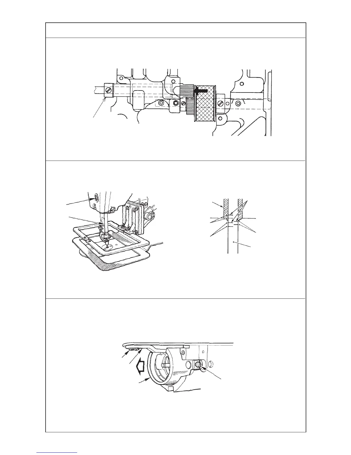
Standard Adjustment
4) Removing the play of the hook shaft
5) Height of the needle bar
6) Removing the oil shield plate of the hook
A
: Engraved line for DP x 5
B
: Engraved line for DP x 17 #18 to #25
C
: Engraved line for DP x 17 #26
Upper engraved
line
1
1
2
3
4
A
B
C
1
2
3
4
1
19
21
Table of Contents
Default Chapter
4
Table of Contents
4
Specifications
6
Configuration
7
Names of Main Unit
7
Names of Switches on the Control Box
8
Function of the Operation Panel Key
9
Adjustments
10
Adjustment of the Main Shaft Components
10
Adjusting the Play of the Main Shaft
10
Installing the Main Motor
10
Adjusting the Main Shaft Sensor
12
Adjusting the Intermediate Presser Components (LK-1942)
12
Adjusting the Position of the Intermediate Presser Cam
12
Position of the Intermediate Presser Bar
14
Height of the Intermediate Presser Adjusting Screw
14
Adjusting the Intermediate Presser Lifting Cylinder Knuckle
16
Adjusting the Wiper Components
16
Position of the Wiper
16
Adjusting the Hook Shaft Drive Components
18
Longitudinal Position of the Main Shaft Sprocket
18
Longitudinal Position of the Hook Driving Shaft Sprocket
18
Backlash of the Hook Shaft Gear
18
Removing the Play of the Hook Shaft
20
Height of the Needle Bar
20
Removing the Oil Shield Plate of the Hook
20
Needle and the Engraved Lines
22
Clearance between the Needle and the Hook
22
Inner Hook Stopper
22
Timing Belt Tension
24
Adjustment of the Thread Trimmer Mechanism Components
26
Adjusting the Thread Trimmer Cam
26
Adjusting the Thread Trimmer Link Stopper Screw
26
Position of the Thread Trimmer Shaft
28
Position of the Cam Installing Link Stopper
28
Position of the Thread Trimmer Magnet Arm
30
Installing Position of the Moving Anf Counter Knives (for H and G Types)
32
Height of the Moving and Counter Knives (for H and G Types)
32
Position of the Moving Knife and the Hot Wire Plate (for Z Type)
34
Contirmation of Operating Timing of the Moving Knife
34
Adjustment of the Tension Release Components
36
Installing Position of the Tension Release Notch
36
Position of the Tension Release Stopper
36
Adjusting the Sensor Components
38
Mechanical Origin
38
Adjusting the y Origin Sensor
38
Adjusting the X Origin Sensor
40
Adjustment of the Feed Mechanism Components
42
Adjusting the Position of the X Motor Base
42
Adjusting the Positions of the X Motor and the y Motor
42
(Adjusting the Backlash of the Driving Gear)
42
Installing the Feed Plate Support Plate
44
Installing the Feed Plate
44
Installing the Feed Bracket
46
Adjusting the Presser Components
48
Adjusting the Presser Cylinder Knuckle
48
Height of the Slider
50
Adjusting the Speed Controller
50
Adjusting the Bobbin Thread Winder Components
48
Position of the Bobbin Winder Driving Wheel
48
Adjustment of the Draw-Out Device Components (for G and Z Types)
52
Position of the Draw-Out Lever
52
Adjustment of the Sewing Components
54
List of the Replacement Components for the Respective Types
54
Kinds and Application of the Hook
55
Stitching Pattern
56
Service Pattern
56
Patterns for Users
56
Memory Switch
58
Operating Method
61
How to Start the Memory Switches
61
How to Finish the Memory Switches
65
Test Mode
66
Operating Method
67
How to Start the Test Mode
67
How to Finish Test Mode
68
How to Check each Test Program no
68
① CP-1 (Input Signal Check)
68
② CP-2 (Origin Retrieval)
71
③ CP-3 (Continuous Operation)
72
④ CP-4 (Revolution Movement)
73
⑤ CP-5 (Solenoid, Solenoid Valve, Status Output and Hot Wire Output)
75
⑥ CP-6 (Hot Wire Output)
76
External Input/Output
77
Parts Grease or Lock-Tite Paint Is Applied
81
Presser Dimensions
83
How to Use Optionals
84
Needle Cooler
84
Installing the Needle Cooler Compl
84
Installing the Solenoid Valve
86
How to Use the Needle Cooler
88
Thread Tension Controller No. 3 / Inverting Clamp Device
88
Installing the Tension Controller No. 3 (B50192220B0)
90
Installing the Solenoid Valve
92
How to Use the Tension Controller No. 3
94
Reverse Sweeping Wiper
96
Installing the Reverse Sweeping Wiper
96
Thread Retaining Wiper
98
Installing the Thread Retaining Wiper
98
Adjusting the Thread Retaining Wiper
98
Feeding Frame Components for Belt (LK-1941)
100
How to Use the Feeding Frame Blank for Belt
100
How to Use the Feed Plate Blank and the Feed Plate Guide for Belt
100
Table of Error Indication
102
Troubles and Corrective Measures
103
Troubles and Corrective Measures (Mechanical Parts)
103
Troubles and Corrective Measures (with Regard to Sewing)
105
Electrical Components
112
Circuit Diagram
118
4
Based on 1 rating
Ask a question
Give review
Questions and Answers:
Need help?
Do you have a question about the JUKI LK-1941 and is the answer not in the manual?
Ask a question
JUKI LK-1941 Specifications
General
Brand
JUKI
Model
LK-1941
Category
Sewing Machine
Language
English
Related product manuals
JUKI LK-1920
67 pages
JUKI LK-1910
67 pages
JUKI LK-1930
264 pages
JUKI LK-1900A
83 pages
JUKI LK-1901A
152 pages
JUKI LK-1900AN
140 pages
JUKI LK-1900A-HS
12 pages
JUKI LK-1903A-305
83 pages
JUKI LK-1900A Series
124 pages
JUKI LK-1900S Series
92 pages
JUKI LK-1900B series
110 pages
JUKI LK-1900BN Series
115 pages
 Loading...