CONTENTS
1. SPECIFICATIONS ......................................................................................1
2. CONFIGURATION......................................................................................2
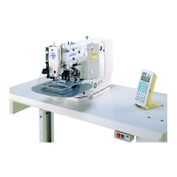
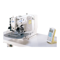
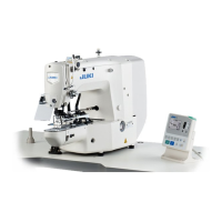
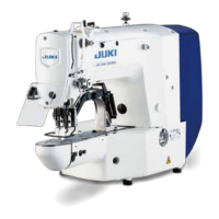
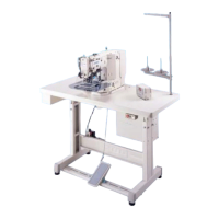
(1) Names of main unit................................................................................................. 2
(2) Names of switches on the control box ................................................................. 3
(3) Function of the operation panel key ..................................................................... 4
3. ADJUSTMENTS .........................................................................................5
(1) Adjustment of the main shaft components.......................................................... 5
1) Adjusting the play of the main shaft................................................................................................ 5
2) Installing the main motor ................................................................................................................ 5
3) Adjusting the main shaft sensor ..................................................................................................... 7
(2) Adjusting the intermediate presser components (LK-1942)............................... 7
1) Adjusting the position of the intermediate presser cam .................................................................. 7
2) Position of the intermediate presser bar ......................................................................................... 9
3) Height of the intermediate presser adjusting screw........................................................................ 9
4) Adjusting the intermediate presser lifting cylinder knuckle ........................................................... 11
(3) Adjusting the wiper components ........................................................................ 11
1) Position of the wiper ..................................................................................................................... 11
(4) Adjusting the hook shaft drive components...................................................... 13
1) Longitudinal position of the main shaft sprocket........................................................................... 13
2) Longitudinal position of the hook driving shaft sprocket ............................................................... 13
3) Backlash of the hook shaft gear ................................................................................................... 13
4) Removing the play of the hook shaft ............................................................................................ 15
5) Height of the needle bar ............................................................................................................... 15
6) Removing the oil shield plate of the hook ..................................................................................... 15
7) Needle and the engraved lines ..................................................................................................... 17
8) Clearance between the needle and the hook ............................................................................... 17
9) Inner hook stopper........................................................................................................................ 17
10) Timing belt tension ..................................................................................................................... 19
(5) Adjustment of the thread trimmer mechanism components............................ 21
1) Adjusting the thread trimmer cam................................................................................................. 21
2) Adjusting the thread trimmer link stopper screw........................................................................... 21
3) Position of the thread trimmer shaft.............................................................................................. 23
4) Position of the cam installing link stopper..................................................................................... 23
5) Position of the thread trimmer magnet arm .................................................................................. 25
6) Installing position of the moving anf counter knives (For H and G types) .................................... 27
7) Height of the moving and counter knives (For H and G types)..................................................... 27
8) Position of the moving knife and the hot wire plate (For Z type) .................................................. 29
9) Contirmation of operating timing of the moving knife ................................................................... 29
(6) Adjustment of the tension release components................................................ 31
1) Installing position of the tension release notch .............................................................................31
2) Position of the tension release stopper ........................................................................................ 31
(7) Adjusting the sensor components...................................................................... 33
1) Mechanical origin.......................................................................................................................... 33
2) Adjusting the Y origin sensor ........................................................................................................ 33
3) Adjusting the X origin sensor ........................................................................................................ 35
(8) Adjustment of the feed mechanism components.............................................. 37
1) Adjusting the position of the X motor base ...................................................................................37
2) Adjusting the positions of the X motor and the Y motor ............................................................... 37
(adjusting the backlash of the driving gear) .................................................................................. 37
3) Installing the feed plate support plate ........................................................................................... 39
4) Installing the feed plate................................................................................................................. 39
5) Installing the feed bracket............................................................................................................. 41
(9) Adjusting the bobbin thread winder components............................................. 43
1) Position of the bobbin winder driving wheel ................................................................................. 43
 Loading...