− 70 −
⑤ CP-5 (Solenoid, solenoid valve, status output and hot wire output)
Checks the respective outputs.
Output No. Table
No. Solenoid, solenoid valve, hot wire output, status output
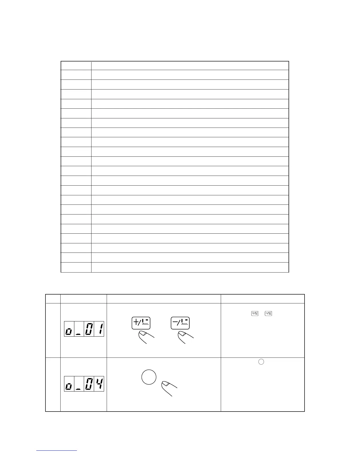
01 Feeding frame valve right/left (AIR_1, _2) : Depending on pedal specifications
02 Presser valve, right (AIR_1)
03 Presser valve, left (AIR_2)
04 Intermediate presser valve (AIR_3)
05 Thread controller No. 3 valve ① (AIR_5) : P95 output
06 Thread trimmer solenoid
07 Wiper valve (AIR_7)
08 Thread draw-out (disk floating) solenoid
09 –
10 –
11 Heat cutter output (hot wire)
12 Needle cooler valve (AIR_4)
13 Thread clamp guide valve (AIR_6)
14 Thread clamp wire valve (AIR_8)
15 Thread controller No. 3 valve ② (AIR_9) : P99 output
16 Presser waiting signal External I/F
17 Start waiting signal External I/F
18 Bobbin thread counter over signal External I/F
19 Needle thread breakage detection error External I/F
20 Temporary stop error External I/F
21 Thread trimming signal at the time of completion of a cycle External I/F
FORWARD
BACK
or
1
2
Output No. is increased or decreased by
pressing down
FORWARD
or
BACK
key.
Output is ON while
READY
key is being pressed
down.
(However, output is automatically turned
OFF when the key is continuously being
pressed for 1 to 7 seconds.)
In addition, ineffective out put is not output
depending on machine model setting.
READY
Indicating section Checking measure Explanation
Step
 Loading...