−23 −
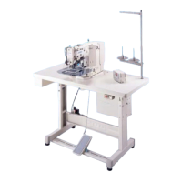
3) Position of the thread trimmer shaft
Make sure that the rear end of thread trimmer shaft 4 aligns with the processed face A of the sewing
machine arm in the state that tension release pin 2 of tension release arm 1 is separated from tension
release notch 3 (thread trimmer stopper support comes in contact with the section B of the sewing
machine arm stopper.).
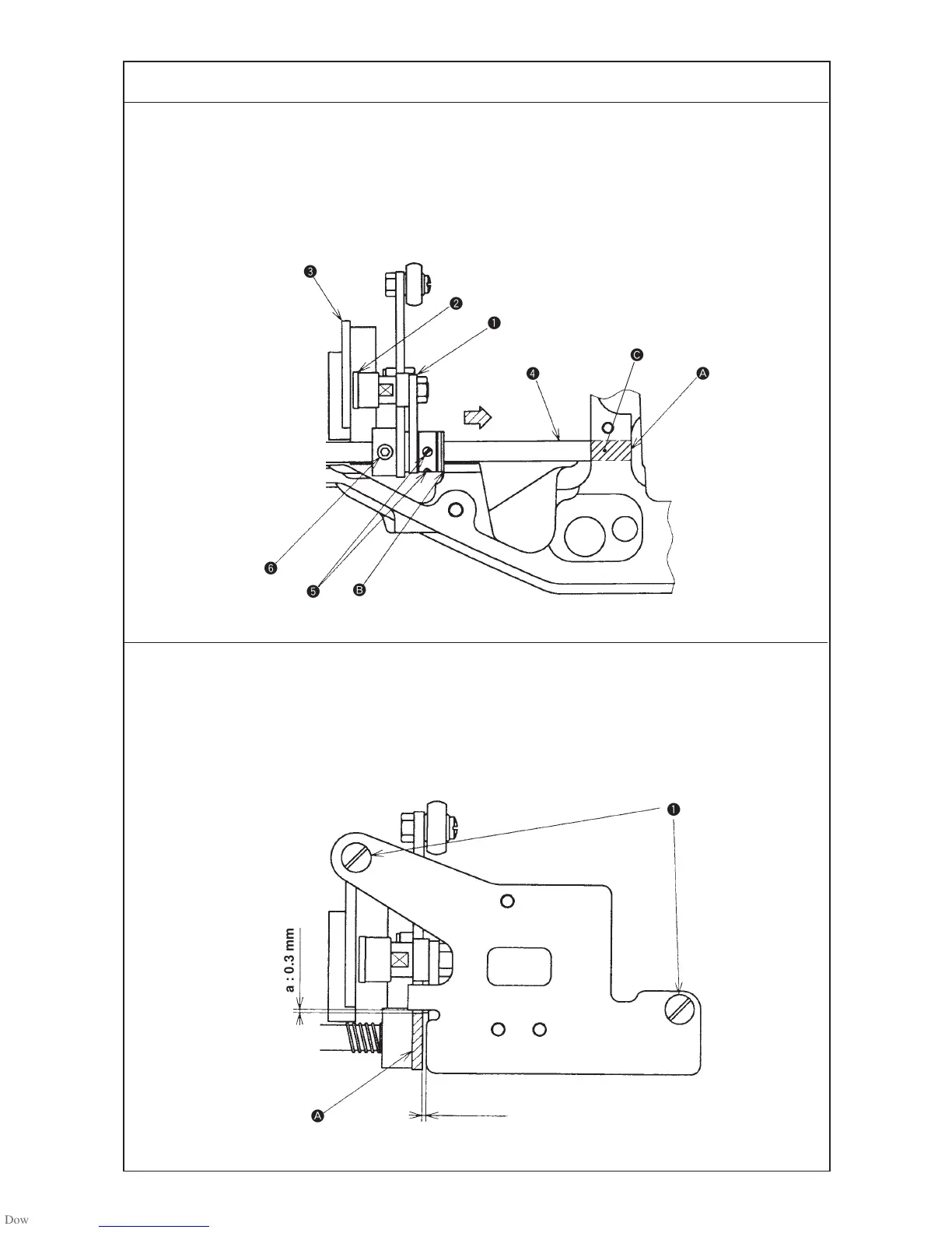
4) Position of the cam installing link stopper
Clearances between the cam installing link notch A and the cam installing link are as follows in the state
that the thread trimmer is separated (the thread trimmer stopper support comes in contact with section B
of the sewing machine arm stopper.).
a : 0.3 mm
b : 0.5 mm or more
Standard Adjustment
b : 0.5 mm or more
 Loading...