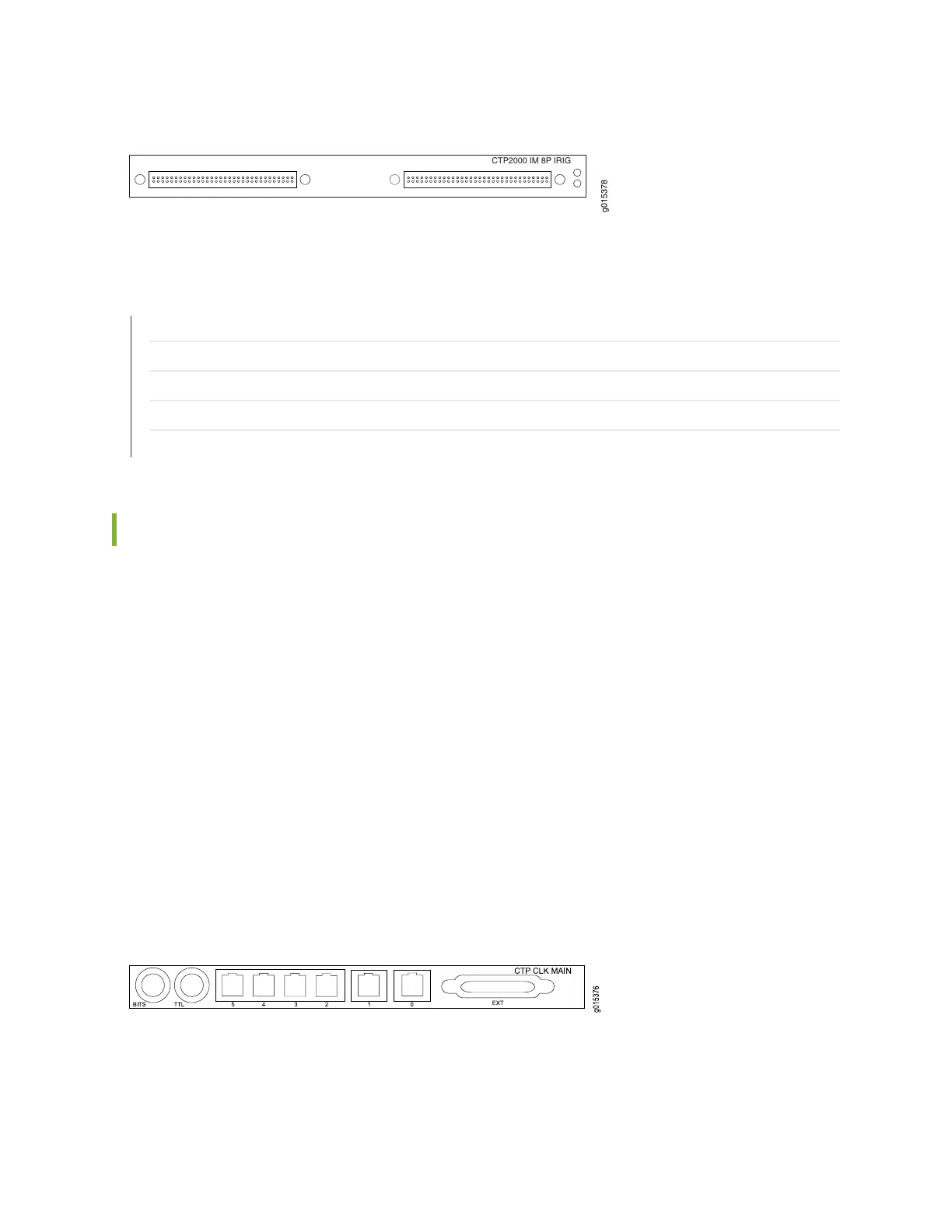
Figure 24: CTP2000 8P-IRIG Interface Module
g015378
CTP2000 IM 8PIRIG
CTP2000 IM 8P IRIG
RELATED DOCUMENTATION
CTP2000 Serial Interface Modules | 11
CTP2000 T1/E1 Interface Module | 13
CTP2000 Compression Module | 13
CTP2000 4WE&M Interface Module | 14
CTP2000 2W-FXS and 2W-FXO Interface Modules | 20
CTP2000 Clock Interface Modules
Clock interface modules provide clock distribution between modules when the backplane is in use by voice
applications.
The clock rear transition module (RTM) is used to input a reference clock into the CTP2000 platform. The
clock RTM is installed in the rear of the chassis behind the first interface module as follows:
•
On CTP2008 devices, the first slot above the processor RTM.
•
On the CTP2024 and CTP2056 devices, the first slot below the processor RTM.
Clock distribution is accomplished through a “hub-and-spoke” configuration composed of a main module
and a spoke module. Clock main modules (Figure 25 on page 27) and clock spoke modules
(Figure 26 on page 28) allow more clock input types in the CTP2000 chassis and provide the capability
for clock distribution when both serial or T1/E1 interface modules and voice modules are installed in the
same CTP2000 chassis.
Figure 25: Clock Main Module
27
 Loading...


