Security Zones and Interfaces 9
Chapter 1: Configuring
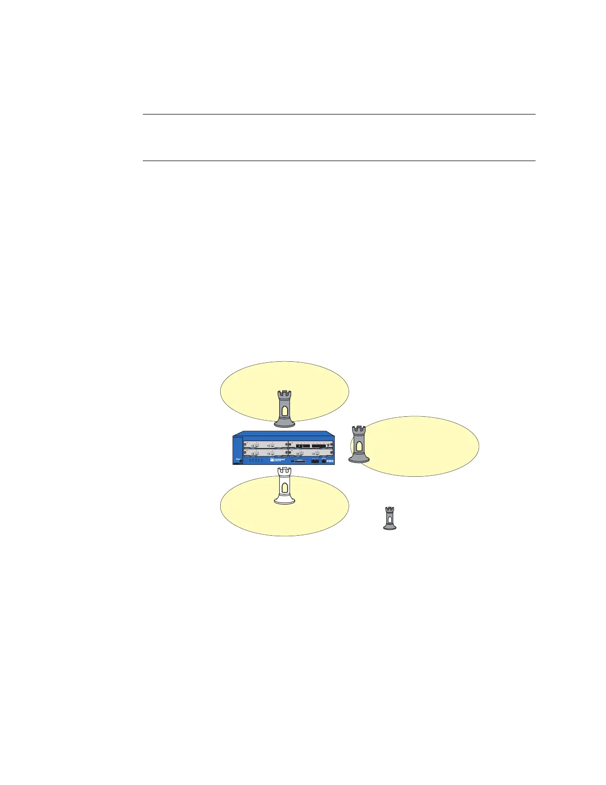
Before you can make use of an interface, you must bind it to a security zone. The
interface then becomes a point of ingress and egress for traffic to and from that
zone. You can bind a single interface to only one security zone, although that one
zone can support multiple different interfaces. To bind an interface to a zone, use
the following command:
set interface interface zone zone
in which interface and zone are the names of the objects you want to bind together.
For example:
set interface ethernet1/1 zone untrust
set interface ethernet1/2 zone dmz
set interface ethernet2/1 zone trust
save
Figure 9: Interfaces Bound to Security Zones
Interface Modes
An ISG 2000 security zone interface can operate in one of three modes: NAT mode,
Route mode, or Transparent mode. NAT mode and Route mode operate at the
Network Layer (Layer 3) in the OSI Model. Transparent mode operates at the Data
Link Layer (Layer 2). Although some interfaces can function in NAT mode while
others concurrently function in Route mode—both modes operating at Layer 3—
the ISG 2000 does not support different interfaces operating concurrently at Layer 3
and Layer 2.
Layer 3 (Route mode and NAT mode) – When you bind an interface to a Layer 3
security zone and give it an IP address, it can operate in either NAT or Route mode.
When an interface is in NAT mode, the NetScreen device translates the source IP
address and source port number on all packets arriving at that interface. When an
interface is in Route mode, the NetScreen device performs Layer 3 routing
operations without modifying the source IP address or port number.
NOTE: The interface names that appear in the get interface output depend on the type
of interface modules installed in the ISG 2000. Most likely the output you see
differs from that shown here.
HA
FLASH
PWR
FAN
ALARM
MOD1
TEMP
MOD2
STATUS
MOD3
ISG 2000
Untrust Zone
DMZ Zone
Trust Zone
ethernet1/2
ethernet1/1
ethernet2/1
Note:
The rook icon represents
a security zone interface.
 Loading...