6.4 Temperature detection T1, T2
NOTICE
• Donot lay KTYor PTC cable of the motor orAIC/LCLlter (also
shielded) together with the control cable !
• KTY or PTC cable only permissible with double shielding within the
motor cable !
6.4.1 Use of the temperature input in KTY mode
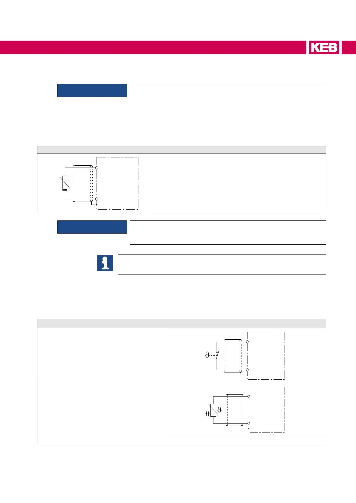
Connection of a KTY sensor
T1
T2
+
KTY84
KTY sensors are poled semiconductors and must be operated in
forward direction! Connect anode to T1 ! Non-observance leads
incorrect measurement in the upper temperature range. Protec-
tion of the motor winding is no longer guaranteed.
NOTICE
KTY sensors may not be combined with other devices. Otherwise
wrong measurements would be the consequence.
Examples for the construction and programming of a temperature control with
KTY84 evaluation can be taken from the F5-AIC Programming manual.
6.4.2 Use of the temperature input in PTC mode
If the temperature input is operated in PTC mode, all possibilities are available for the
userwithinthespeciedresistancerange.Thiscanbe:
Wiring example in PTC mode
Thermal contact (NC contact)
T1
T2
Temperature sensor (PTC)
T1
T2
continued on the next page
41
CONNECTION OF THE COMBIVERT F5-AIC
 Loading...
