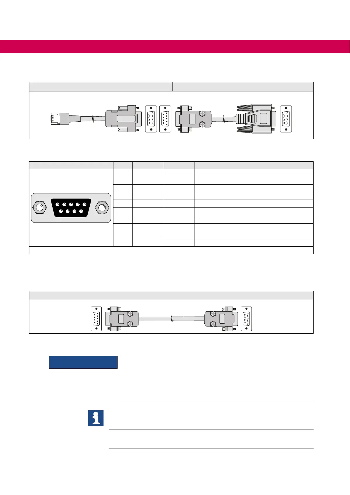
Required accessories:
Adapter RJ45/DSub-9 Converter HSP5/RS232
HSP5
TTL
PC
1
5
6
9
1
5
6
9
1
5
6
9
C0F50C0-0020
8.3.2 Description of the RS232/485 interface X6C
X6C PIN RS485 Signal Meaning
9 8 7 6
5 4 3 2 1
9 8 7 6
1 - - reserved
2 - TxD Transmission signal RS232
3 - RxD Receive signal RS232
4 A‘ RxD-A Receive signal A RS485
5 B‘ RxD-B Receive signal B RS485
6 - VP Supply voltage +5 V
(I
_max = 50 mA)
7 C/C‘ DGND Data reference potential
8 A TxD-A Transmission signal A RS485
9 B TxD-B Transmission signal B RS485
Table 18: Description of the RS232/485 interface X6C
8.3.3 Connection of the RS232 interface
A RS232 cable is required to connect the interface operator with a PC.
Serial cable to connect the operator with a PC
1
5
6
9
1
5
6
9
8.3.4 Connection of the RS485 interface
NOTICE
The following instructions must be observed to prevent malfunctions at
the RS485 interface:
• Use CAT 5 cable (in pairs, twisted and shielded cable)
• Ground to one side (prior to the lower interference side)
• Attachterminatingresistorsof120Ωtobothendsofthebus
If CAT 7 cable is used (by way of derogation from our recommendation) lay the
interior shield each to the transmitter.
If malfunctions still occur, it is possible to use a biasing. However, this shall be
done only once at the bus (preferably at the master).
56
OPERATION OF THE CONTROL
 Loading...
