PIN Function Name Default assignment Description
24 Relay 1 / NO contact RLA
Error messages (error)
Programmable relay output 1 (ter-
minal X2A.24...26);
Programmable relay output 2 (ter-
minal X2A.27...29)
Specication,controlandprogram-
ming of the relay outputs max. 30V
DC, 0.01...1A
25 Relay 1 / NC contact RLB
26
Relay 1 / switching
contact
RLC
27 Relay 2 / NO contact FLA
Ready for operation
(Uic loaded)
28 Relay 2 / NC contact FLB
29
Relay 2 / switching
contact
FLC
Figure 14: Assignment of the terminal block X2A
7.1.2 Connection of the control
In order to prevent a malfunction caused by interference voltage supply on the control
inputs, the following directions should be observed:
• Use shielded / drilled cables.
• Lay shield on one side of the drive converter onto earth potential.
• Lay control and power cable separately (about 10...20 cm apart); Lay crossings in
a right angle.
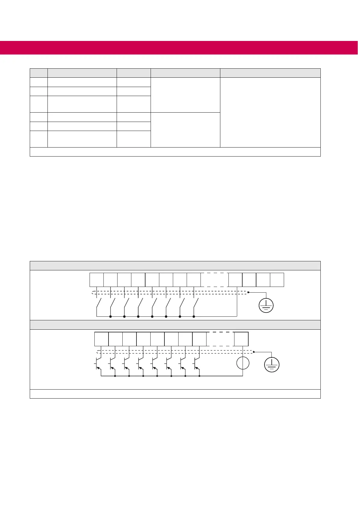
7.1.3 Digital inputs
Using of the internal voltage supply
10 11 12 13 14 15
16 17 20
21 22 23
Using of an external voltage supply (e.g. PLC)
10 11 12 13 14 15
16 17 23
+
Figure 15: Digital inputs
50
CONNECTION OF THE CONTROL
 Loading...
