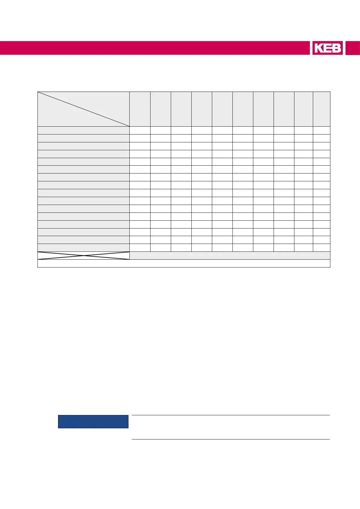
Coolant inlet temperature [°C] is depending on ambient temperature and
air humidity
Air humidity in %
Surrounding
temperature in °C
10 20 30 40 50 60 70 80 90 100
-25 -45 -40 -36 -34 -32 -30 -29 -27 -26 -25
-20 -42 -36 -32 -29 -27 -25 -24 -22 -21 -20
-15 -37 -31 -27 -24 -22 -20 -18 -16 -15 -15
-10 -34 -26 -22 -19 -17 -15 -13 -11 -11 -10
-5 -29 -22 -18 -15 -13 -11 -8 -7 -6 -5
0 -26 -19 -14 -11 -8 -6 -4 -3 -2 0
5 -23 -15 -11 -7 -5 -2 0 2 3 5
10 -19 -11 -7 -3 0 1 4 6 8 9
15 -18 -7 -3 1 4 7 9 11 13 15
20 -12 -4 1 5 9 12 14 16 18 20
25 -8 0 5 10 13 16 19 21 23 25
30 -6 3 10 14 18 21 24 26 28 30
35 -2 8 14 18 22 25 28 31 33 35
40 1 11 18 22 27 31 33 36 38 40
45 4 15 22 27 32 36 38 41 43 45
50 8 19 28 32 36 40 43 45 48 50
Coolant inlet temperature in °C
Table 24: Coolant inlet temperature [°C] is depending on ambient temperature and air humidity
10.1.5 Connection to the cooling system
• Screwintheconnectingductsaccordingtoinstallationinstructionsfortting
0000650-G14K.
• heconnectiontothecoolantmustbecarriedoutwithexible,pressure-resistant
hoses and secured with clamps.
• Payattentiontouxdirectionandchecktightness!
• ThecoolingowmustalwaysbestartedbeforestartingtheCOMBIVERT.
The connection to the cooling system can occur as closed or open cooling circuit. The
connection to a closed cycle cooling circuit is recommended, because the danger of
contamination of coolant is very small. Preferably also a monitoring of the pH value of
the coolant should be installed.
Pay attention to a corresponding conductor cross-section at required equipotential
bonding in order to avoid electro-chemical procedures.
Otherelementsinthecoolingcircuitsuchaspumps,mixingvalves,shut-ovalves,ven-
tilation etc. must be attached according to the cooling system and the local conditions.
NOTICE
A discontinuous mode is not recommended, since this leads to a reduc-
tion of the service life.
65
COOLING SYSTEM
 Loading...
