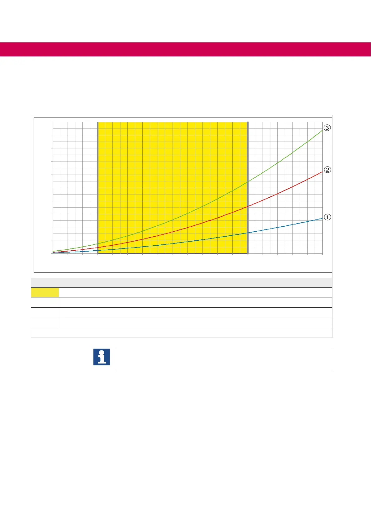
10.1.5.1 Pressuredropoftheheatsinkdependingontheowrate
The pump capacity required for the COMBIVERT F5 is derived from the following spec-
ications,whicharerepresentedinthediagramchapter„Connectionschemeforacool-
ing circuit (series connection)".
bar
l/min
0,0
0,4
0,8
1,2
1,6
2,0
2,4
2,8
3,2
3,6
4,0
4 6 8 10 12 14 16 18 20 22 24 26 28 30 32 34 36
38
40
Legend
Recommended working range 10...30 in l/min
①
Single device
②
Series connection of two modules (Master/Slave)
③
Series connection of three modules (Master/Slave/Slave)
Figure 27: Pressure drop of the heat sink depending on the ow rate
The choice of the connection scheme (series or parallel connection) of the
coolant circuit is dependent on the heat power dissipation and the selected
switching frequency of the drive converter system.
66
COOLING SYSTEM
 Loading...
