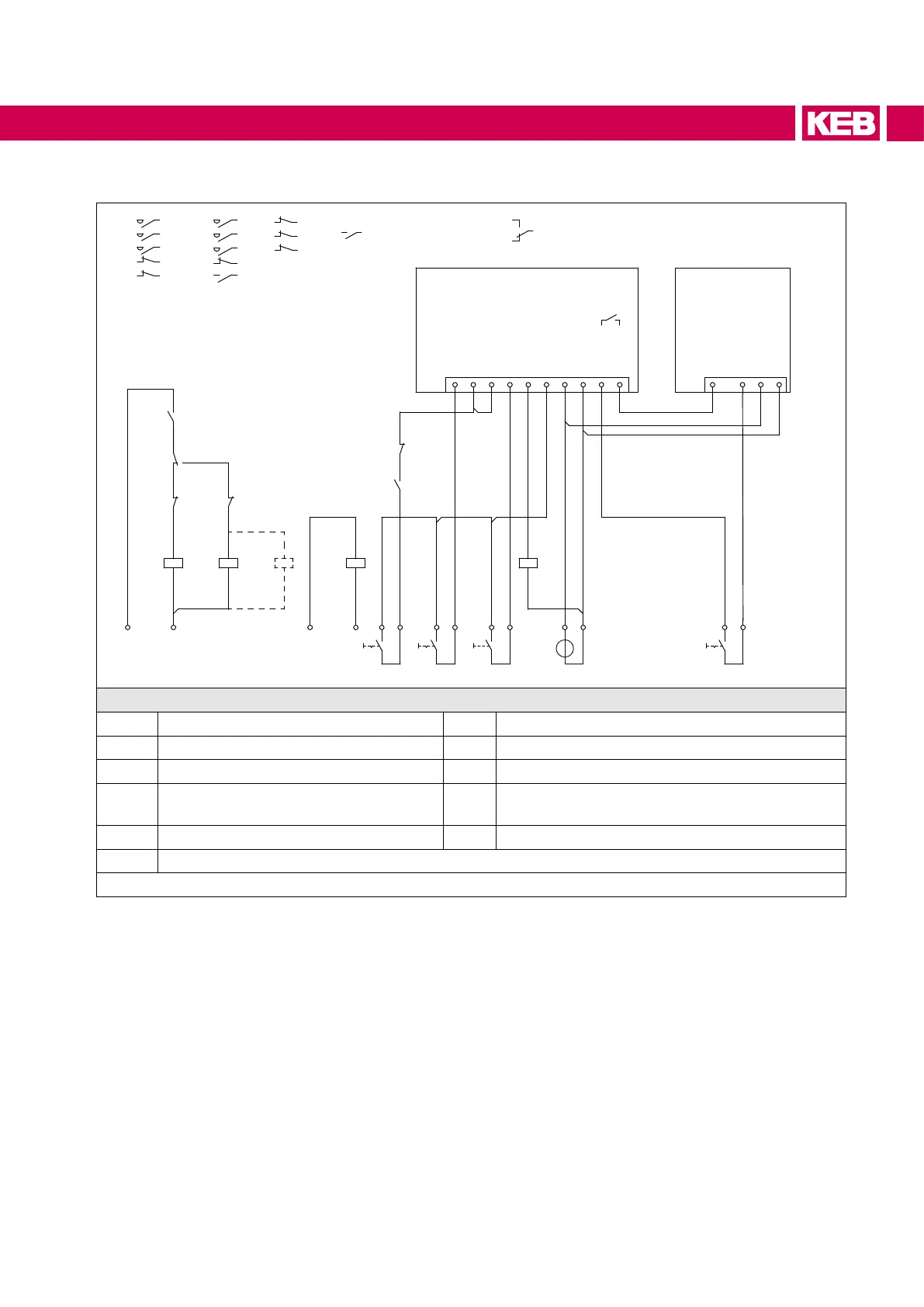
6.6.5 Circuit example for the control circuit
-U6-U5
-K1-K2 -K3
-K2
-K3
-K5
-K1
-K3
-K5
-K2
-S1 -S2 -S3 -S4
10 (I1)
11 (I2)
16 (ST)
17 (RST)
18 (O1)
20 (Uout)
21 (Uin)
22 (0V)
27 (FLA)
29 (FLC)
16 (ST)
20 (Uout)
21 (Uin)
22 (0V)
X2A X2A
L N
+ -
Uout
Uout
Uout
Uout
ST I1
RST
ST
0VUin
1
3
5
11
21
2
4
6
12
22
1
3
5
11
13
2
4
6
12
14
13 14
12
14
11
24Vdc
+
-G2
21
22
13
14
13
14
11
11
12
11
12
1412
-K4
A1
A2
A1
A2
A1
A2
A1
A2
A1
A2
13
14
13
14
13
14
13
14
1
3
5
2
4
6
Legend
K1 Couplingrelay(controlon/o) S2 Second setpoint (customer)
K2 Pre-charging contactor S3 Error reset
K3 / K4 Main contactor S4 External release for drive converter
K5
Coupling relay (max. 50 mA) for main
contactor
U5 COMBIVERT F5-AIC
S1 External control release U6 Drive converter
G2 24 V DC supply (recommended)
Figure 12: Circuit example for the control circuit
47
CONNECTION OF THE COMBIVERT F5-AIC
 Loading...
