6.6.6 Functional description
The pre-charging contactor (K2) is switched by applying a 24 V DC voltage to the cou-
pling relay (K1). If the DC link voltage reaches an adjustable value (480 V DC at factory
setting LE.04) output O1 is set and the coupling relay switches (K5). K5 disconnects the
pre-charging contactor K2 and switches the main contactor K3. Further charging of the
DClinkisdoneviathemaincontactorandAICorLCLlter.
The modulation is suppressed via internal programming (OA, IA) as long as an adjust-
able threshold value (LE.04) is reached and a responding waiting period (di.48) has
expired.
The control release is set by switch (S1), if the pre-charging contactor K2 drops out and
the main contactor has tightened. A delay time (di.42) starts simultaneously with the
control release by input I2 after that the modulation is released.
Phase position and phase sequence (counterclockwise/clockwise) of the mains voltage
are detected now. Thereafter, the DC link voltage is controlled to the preset setpoint
(oP.03). If this value is reached, the relay output 2 (R2) switches after one second. The
drive converter can modulate if the external control release of the drive converter (S4)
is set.
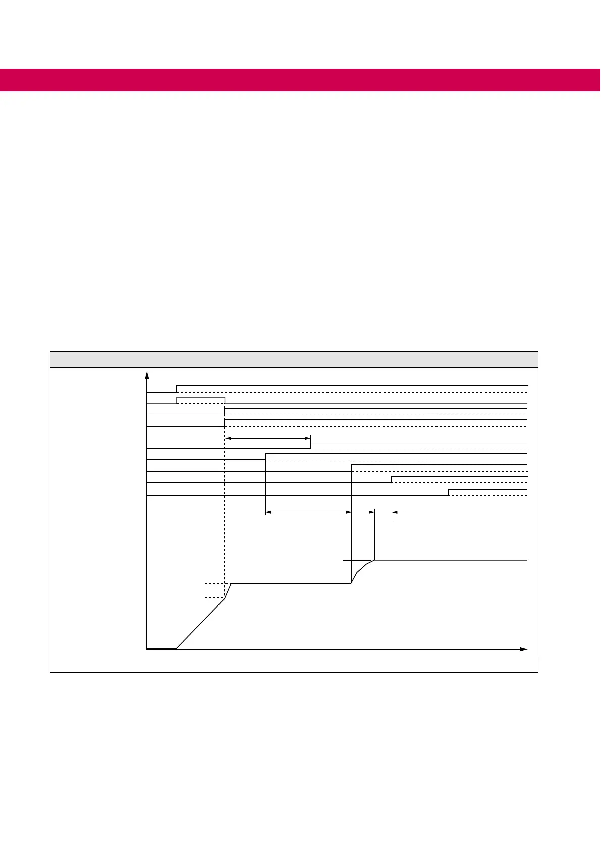
Flow chart switch-on procedure
S1
S4
Modulation (AIC)
K1
K2
O1 (AIC)
R2 (AIC)
OA->IA (AIC)
LE.00/04
565V
oP.03 (680V)
5s (di.48)
5s (di.42)
Udc
1s
K3
Figure 13: Flow chart switch-on procedure
48
CONNECTION OF THE COMBIVERT F5-AIC
 Loading...
