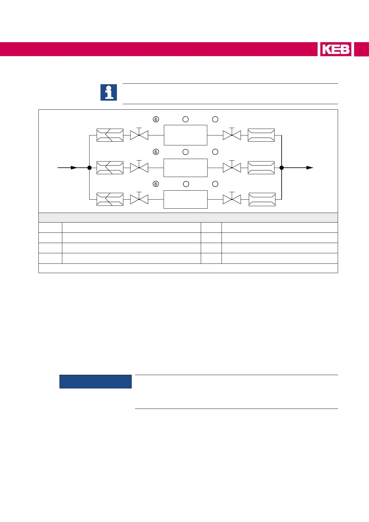
10.1.5.4 Connection scheme for a cooling circuit (parallel connection)
This connection scheme is only an installation proposal and does not replace
professional planning and execution!
①
➃ ➄
② ③②
① ② ③②
① ② ②
Master
Slave
Slave
③
7
7
7
8
8
8
1/2“
1/2“
1/2“
1/2“
1/2“
1/2“
3/4“ 3/4“
Legend
①
Flow limiter 10...40 l/min
⑤
Returnowentiresystem
②
Ball valve/stop valve
⑥
Precharging drive converter
③
Flow switch (e.g. Sika VH / VK)
⑦
Returnowdriveconverter
④
Pre-run entire system
⑧
Drive converter
Figure 30: Connection scheme for a cooling circuit
The connection of the coolant circuit to the drive converter system as a parallel execu-
tion is also possible in the rated operation and mandatory for special applications.
Itshouldbenotedthattheuseofowcontrollerandatemperaturemonitoringismanda-
toryrequired.ThecoolingowmustalwaysbestartedbeforestartingtheCOMBIVERT.
Other elements in the cooling circuit such as pumps, shut-o valves, ventilation etc.
must be attached according to the cooling system and the local conditions.
The total volume ow depends on the specied heat power dissipation of the drive
converter system (see technical data). The data apply for rated operation. Special ap-
plicationsonrequest.Therelationshipsbetweenheatpowerdissipation,owandtem-
peraturedierenceareshowninthediagram„Volume ow in dependence of the heat
power dissipation and temperature dierence“.
NOTICE
Themaximumtemperaturedierence(ΔT)betweenpre-runandreturn
owmaynotexceed7K.Ifthevolumeow(above30l/minpermod-
ule) is selected too large, increases the risk of erosion in the liquid
cooler.
10.1.6 Decommissioning
Thecoolingcircuitmustbecompletelyemptyifaunitshallbeswitchedoforalonger
period. The cooling circuit must be blown out additionally with compressed air at tem-
peratures below 0°C.
69
COOLING SYSTEM
 Loading...
