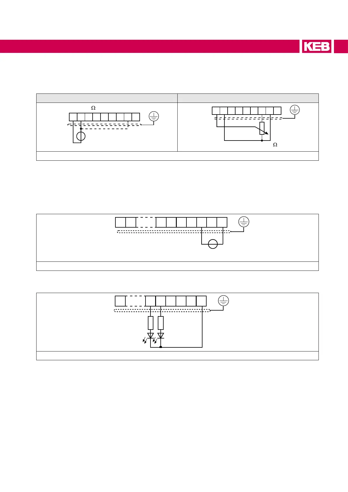
7.1.4 Analog inputs
Connect not connected setpoint inputs to the analog ground to avoid setpoint changes !
Analog setpoint setting external Analog setpoint setting internal
123456789
PE
+
123456789
Figure 16: Analog inputs
7.1.5 Voltage input external power supply
When the power unit is switched o the control remains in operation by an external
voltagesupplyofthecontrolboard.Topreventundenedconditionsatexternalpower
supply, generally the supply unit and then the AIC unit should be switched on.
10 11 17 18 19 20
21 22 23
20…30 V ±0 % / 1 A DC smoothed
Figure 17: Voltage input external power supply
7.1.6 Digital outputs
10 18 19 20
21 22 23
max. 50 mA DC for both outputs
Figure 18: Digital outputs
51
CONNECTION OF THE CONTROL
 Loading...
