Card Connections and Installation
2-3
2.3.2 Card connectors
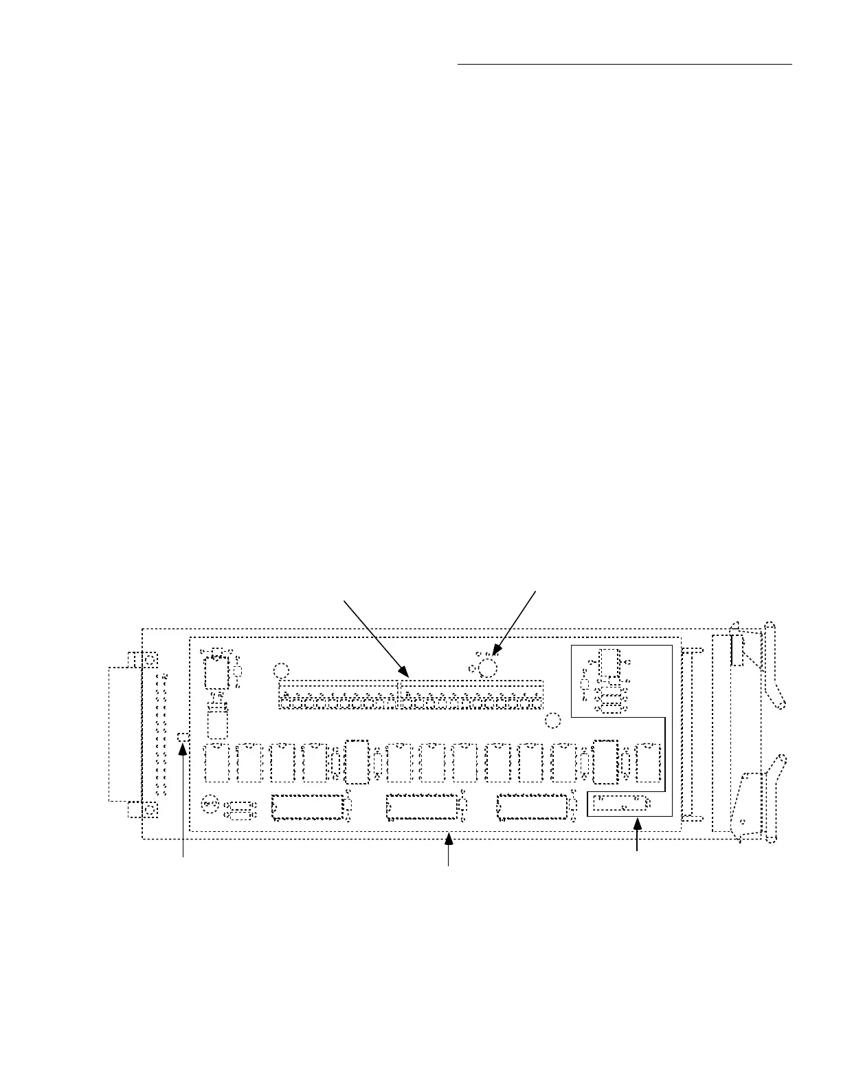
Figure 2-2 shows the input/output connectors for the card.
Card connections include:
• CH 2-10 (channels 2-10): HI and LO input terminals
are provided for each of the nine channels on the card.
NOTE
Channels 5 and 10 have current-limiting
resistors installed. Path resistance for
these two channels is approximately
240
Ω
.
• OUT A: HI and LO output connections for all nine
channels in the 2-pole mode or channels 2-5 in the 4-
pole mode.
• OUT B: HI and LO output connections for channels 7-
10 in the 4-pole mode.
In order to gain access to the connections, first open the plas-
tic shield by pressing in on the locking tab. Swing the shield
away from the circuit board.
Locking Tab
Plastic Shield
Input/Output Connectors
Reference Junction Sensor
Reference Junction Circuitry
HI LO
CH 2 OUT A OUT B
HI LO
CH 3
HI LO
CH 4
HI LO
CH 5
HI LO
CH 6
HI LO
CH 7
HI LO
CH 8
HI LO
CH 9
HI LO
CH 10
HI LO HI LO
Figure 2-2
Card connectors
2.3.3 Wiring procedure
Perform the following procedure to wire circuitry to the
screw terminals on the scanner card.
WARNING
Make sure all power is off and any
stored energy in external circuitry is
discharged before connecting or discon-
necting wires.
CAUTION
Mechanical shock may open or close
latching relays on the scanner card. Be-
fore enabling any external sources, open
all relays by inserting the Model 2001-
TCSCAN into the DMM and turning on
the power.

 Loading...
