Operation
3-31
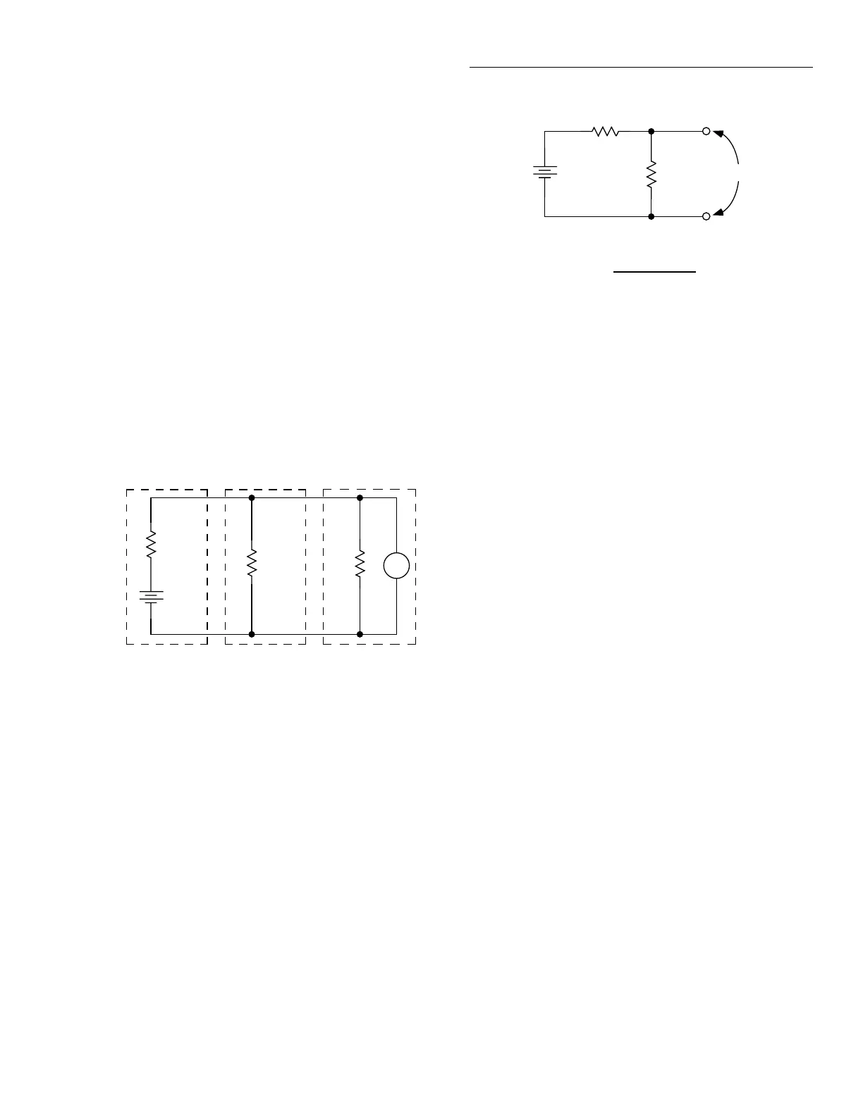
3.13.2 Path isolation
The path isolation is simply the equivalent impedance be-
tween any two test paths in a measurement system. Ideally,
the path isolation should be infinite, but the actual resistance
and distributed capacitance of cables and connectors results
in less than infinite path isolation values for these devices.
Path isolation resistance forms a signal path that is in parallel
with the equivalent resistance of the DUT, as shown in
Figure 3-7. For low-to-medium device resistance values,
path isolation resistance is seldom a consideration; however,
it can seriously degrade measurement accuracy when testing
high-impedance devices. The voltage measured across such
a device, for example, can be substantially attenuated by the
voltage divider action of the device source resistance and
path isolation resistance, as shown in Figure 3-8. Also,
leakage currents can be generated through these resistances
by voltage sources in the system.
3.13.3 Channel resistance
The on resistance of channels 5 and 10 is approximately
<240Ω. For this reason, you should not use channels 5 and
10 for low-to-medium 2-wire resistance measurements
(<100kΩ). For example, measuring a 1kΩ resistor using
channel 5 or channel 10 will result in an error of more than
25%.
3.13.4 Magnetic fields
When a conductor cuts through magnetic lines of force, a
very small current is generated. This phenomenon will fre-
quently cause unwanted signals to occur in the test leads of a
scanning system. If the conductor has sufficient length, even
weak magnetic fields like those of the earth can create suffi-
cient signals to affect low-level measurements. Two ways to
reduce these effects are: (1) reduce the lengths of the test
leads, and (2) minimize the exposed circuit area. In extreme
cases, magnetic shielding may be required. Special metal
with high permeability at low flux densities (such as mu met-
al) is effective at reducing these effects.
Figure 3-7
Path isolation resistance
R
E
DUT
DUT
R
PATH
V
R
IN
DUT
Scanner
Card
Model 2001
= Source Resistance of DUT
= Source EMF of DUT
= Path Isolation Resistance
= Input Resistance of Model 2001
R
DUT
E
DUT
R
PATH
R
IN
Figure 3-8
Voltage attenuation by path isolation resistance
R
E
DUT
DUT
R
PATH
E
OUT
R
PATH
R
DUT
R
PATH
+
=
E
DUT
E
OUT

 Loading...
