Card Connections and Installation
2-8
2.4.3 Resistance connections
■
2-Pole connections
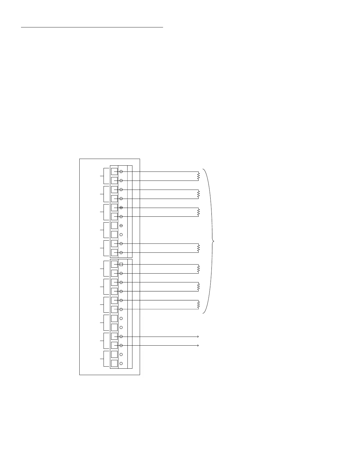
Figure 2-7 shows typical 2-pole resistor test connections.
The 2-pole resistance configuration can be used to test up to
seven DUTs.
NOTE
Channels 5 and 10 should not be used to
switch 2-wire resistance measurements
because of the relatively high path resis-
tance (
≅
240
Ω
) of these two channels due
to the factory-installed current-limiting re-
sistors. (Unless the card is modified; see
paragraph 4.8.)
■
4-Pole connections
Typical 4-pole resistance connections are shown in Figure 2-
8. This general configuration can be used with channel pairs
2-5 and 7-10 to scan:
• 4-wire resistance measurements.
• 4-wire RTD temperature measurements.
Resistors
Under Test
HI HI LO HI LO HI LO HI LO HI LO HI LO HI LO HI LO HI LO HI LO
CH 2
CH 3
CH 4
CH 5
OUT A
CH 6
CH 7
CH 8
CH 9
CH 10
OUT B
2001-TCSCAN Card
HI
LO
LO
To DMM Input Jacks
NOTE: Do not use channels 5 and 10
for 2-wire resistance measurements
Figure 2-7
Typical connections for 2-wire resistance scanning

 Loading...
