Service Information
4-4
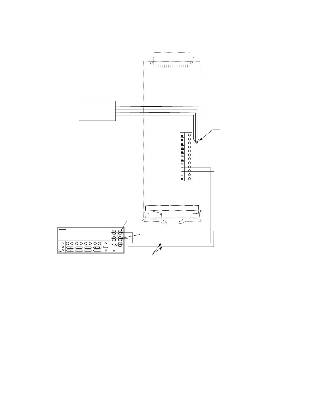
4.3.5 Path resistance tests
Perform the following steps to verify that the path resistance
of each channel is with specified values.
1. Connect the HI and LO terminals of all nine channel in-
puts together using #22AWG solid copper jumper wires
(see Figure 4-2).
Thermistor
Probe
Model 2001-TCSCAN installed in
Model 2001#1 (Not shown)
Reference
Thermometer
OUT A HI
OUT A LO
Copper Wires
Input
LO
Model 2001 #2
(Measure DCV)
NEXT
DISPLAY
PREV
POWER
DCV ACV DCI ACI Ω2 Ω4
FREQ TEMP
REL TRIG STORE RECALL
INFO LOCAL CHAN SCAN CONFIG MENU EXIT ENTER
RANGE
AUTO
FILTER MATH
RANGE
2001 MULTIMETER
SENSE
Ω 4 WIRE
HI
INPUT
LO
INPUTS
CAL
500V
PEAK
FR
FRONT/REAR
2A 250V
AMPS
350V
PEAK
1100V
PEAK
Input
HI
Figure 4-1
Connections for reference junction test
NOTE
Make sure that all jumper wires are clean
and free of oxides.
2. Connect the output cables to OUT A HI and LO, as
shown in Figure 4-2.
3. With the power off, install the scanner card in the Model
2001 Multimeter.

 Loading...
