Service Information
4-14
4.6.2 Relay control
Card relays are controlled by serial data transmitted via the
relay DATA line. A total of three bytes are shifted in serial
fashion into latches located in the card relay driver ICs. The
serial data is clocked in by the CLOCK line. As data over-
flows one register, it is fed out the Q’S line of the register
down the chain.
Once all three bytes have shifted into the card, the STROBE
line is set high to latch the relay information into the Q out-
puts of the relay drivers, and the appropriate relays are ener-
gized (assuming the driver outputs are enabled, as discussed
below). Note that a relay driver output goes low to energize
the corresponding relay.
4.6.3 Switching circuits
Relays K101 through K106 and K108 to K113 perform input
switching, while K107 configures the card for 2-pole or 4-
pole operation.
4.6.4 Power-on safeguard
A power-on safeguard circuit, made up of U104 and associ-
ated components, ensures that relays do not change state on
power-up and power-down. This circuit disables all relay ac-
tuation during power-up and power-down periods by holding
the OE (output enable lines) high during these periods.
4.6.5 Reference junction
The reference junction for cold junction compensation is
made up of U105 and associated components. Calibration
adjustment is provided by R151.
4.7 Troubleshooting
4.7.1 Troubleshooting equipment
Table 4-2 summarizes recommended equipment for trouble-
shooting the Model 2001-TCSCAN.
4.7.2 Troubleshooting access
In order to gain access to the scanner card circuit board to
measure voltages under actual operating conditions, perform
the following steps:
1. Turn off the Model 2001 power, and disconnect the line
cord and all other equipment.
2. If wires are connected to the scanner card, remove the
scanner card from the multimeter.
3. Remove the Model 2001 cover as follows:
A. Remove the handle by rotating it to align the arrows
on the handle mounting ears. Pull out and remove
the handle.
B. Remove the screws that secure the handle mounting
ears, then remove the ears.
C. Remove the screws that attach the rear bezel to the
case, then remove the bezel.
D. Remove the bottom screw that grounds the case to
the chassis.
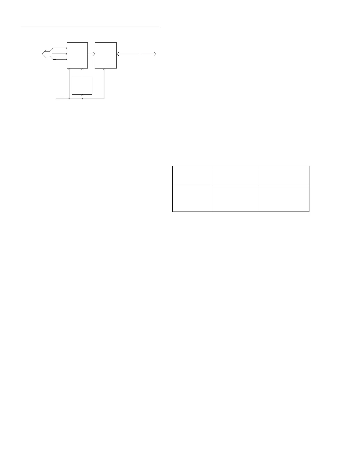
Figure 4-9
Block diagram
To 2001
Multimeter
Clock
Data
Strobe
Enable
+5V
User Connections
Power-on
Reset
U104
Relays,
K101-K113
Relay
Drivers
U101-U103
Table 4-2
Recommended troubleshooting equipment
Description
Manufacturer
and model Application
Multimeter Keithley 2001 DCV checks
Oscilloscope TEK 2243 View logic wave-
forms

 Loading...
