107
105
106
10
- 54 -
FUEL SYSTEM
KD 225_315_350_400_440 Workshop Manual_cod. ED0053029330_1° ed_ rev.00
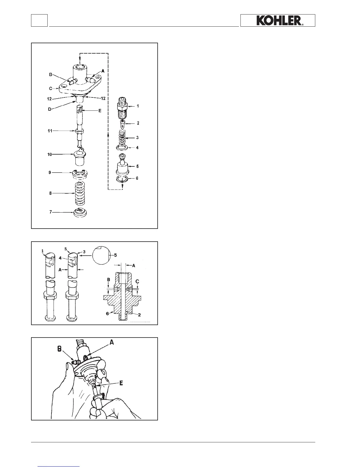
Injection pump components and disassembly
1 Deliveryunion
2Filler
3 Spring
4Gasket
5Valve
6Gasket
7Springretainer
8Spring
9 Springplate
10Rack
11Plunger
12Pin
A=Fueloutletunion
B =Fuelintakeunion
C=Fastening
D=Barrel
E=RHhelix
Demountincompliancewiththenumericorder.
Plate9is heldrmbypins 12.Leverupbyinserting a toolbetween
theplateandthebodyofthepump.
Thevolumeshiftedbydeliveryvalve 5 is 15
mm
3
inthepumpofKD
315-350and25mm³inthepumpofKD225is21mm
3
inthepumpof
KD400/440
Injection pump, body, plunger and delivery valve
Components: Dimensionsmm:
1 Deliveryvalve A=5.50(nominaldiam.)225-315-350
2 Barrel A=7,00(nominaldiam.)400-440
3Plunger A=6,00(nominaldiam.)315-350EPA
4 Righthelix B=2.00/2.03
5Delaynotch C=1.50/1.53
6Pumpbody
7 Collar
Note: The injection pump installed in engines for small vehicles,
soundproof generating sets, EPA and KD 400-440 engines,
arecharacterisedbytheinclusionofacollar1whichcontribu-
testonoise-reduction.
Injection pump retting
The plunger is tted with helix E facing towards the outlet union A;
ifitismistakenlyttedwiththehelixfacingtheintakecouplingBthe
injectionpumpnolongeroperates(thereisnodangerofengineru-
naway);completerettingfollowingg.107.
 Loading...