122
123
124
11
- 61 -
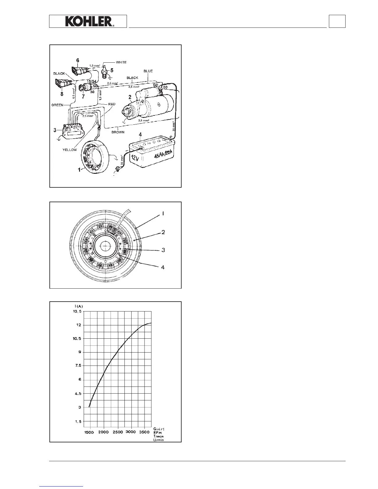
ELECTRICAL SYSTEM
12V, 12A electric ignition diagram
Components:
1Alternator
2Startermotor
3 Voltageregulator
4 Battery
5 Pressureswitch
6Oilpressurelight
7Keyswitch
8Batterycharginglight
Alternator
Components:
1Ringgear
2 Flywheel
3Rotor
4Stator
Fixingscrewsmustbetightenedto1.2Nm.
Note: The rotor is made up by a plastoferrite ring which is xed to
ywheelwhilethestatorismountedonthecrankcase.
Alternator battery charger graph (12V, 12A)
Thistesthasbeencarriedoutafterthermalstabilizationat20°Cfor
2minutesat3000r.p.m.withconstantbatteryvoltageof12.5V.
The value of the power supplied with reference to the curve may
changeinarangebetween+10%and-5%.
KD 225_315_350_400_440 Workshop Manual_cod. ED0053029330_1° ed_ rev.00
Note: The battery, which is not supplied by KOHLER, should have
12Vnominalvoltageratingandacapacityofnotlessthan44
Ah/210Amp.offastdischargeintensity.
 Loading...