Product description Service and Repair Manual
Function description
4 Fuel filter 5.4 B704 and B705 – HP pump
(Bank A and B)
10 Distribution Block
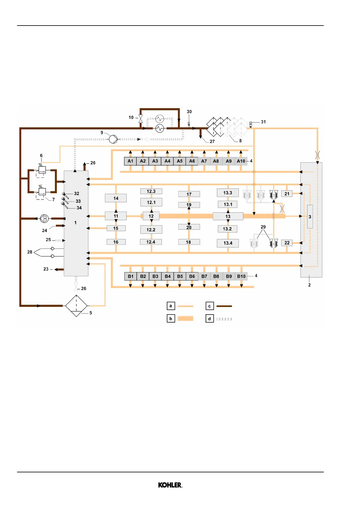
1.3.2 Lubricating system
Engine oil diagram
Fig. 22: Engine oil diagram
a Filtered oil c Non-filtered oil
b Main oil channel d Depending on engine config-
uration
1 Oil tank 12.2 Cam follower bearings B 19 Cylinder heads A
2 Aggregate support 12.3 Roller bearings A 20 Cylinder heads B
3 Support bearing 12.4 Roller bearings B 21 HT coolant pump
4 Piston cooling jets 13 Crankshaft bearings 22 LT coolant pump
5 Centrifugal filter 13.1 Conrods A 23 Preheating port
6 Pressure Control Valve 13.2 Conrods B 24 Oil filling
7 Pressure Safety Valve 13.3 Pistons pins A 25 Automatic oil refill
8 Spin-on oil filter 13.4 Pistons pins B 26 Drain port
9 Prelubricating pump 14 Support bearing Flywheel 27 Oil sampling
10 Bypass valve for cold start 15 Gear box 28 CCV
11 Intermediate gears
Flywheel
16 HP Pump 29 Turbochargers
See next page for continuation of the image legend
32
© 2021 by Kohler Co. All rights reserved.
KD62V12 33525088601_7_1 EN_US
2021-07
 Loading...