Service and Repair Manual Product description
Function description
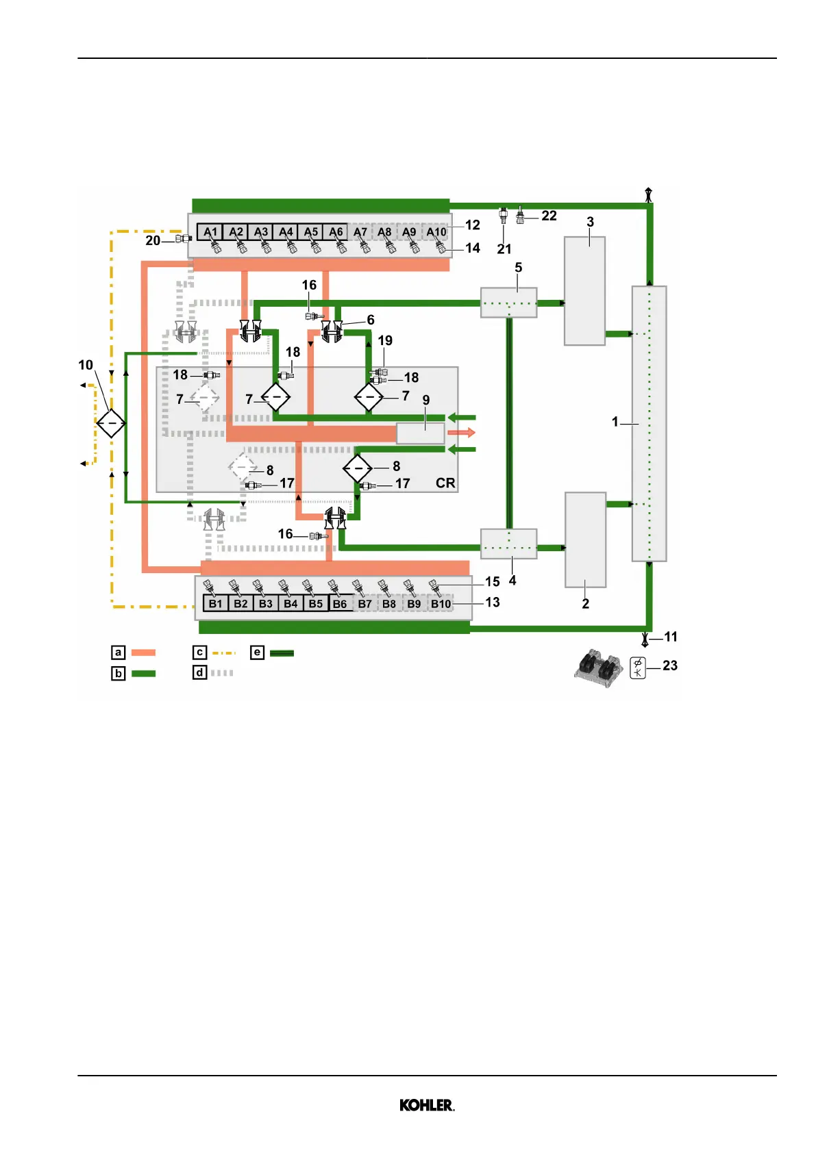
1.3.4 Charge air system
Charge air diagram
Fig. 25: Charge air diagram
a Exhaust gas c Oil vapor e For odd number of turbo-
chargers only
b Fresh air d Depending on engine config-
uration
CR Customer responsibility
1 Aggregate support 6 Turbocharger 11 Venting point
2 Charge air cooler - B side 7 Air filter - A side 12 Engine A bank
3 Charge air cooler - A side 8 Air filter - B side 13 Engine B bank
4 Elbow - B side 9 Exhaust catalyst
5 Elbow - A side 10 Blowby filters
Sensors list
14 B785x - Exhaust gas temper-
ature on cylinder Ax (optional)
18 B780 - Air intake pressure
switch - A side (clogging)
22 B707 - Charged air tempera-
ture A after charge air cooler
15 B786x - Exhaust gas temper-
ature on cylinder Bx (optional)
19 B749 - Air intake temperature
- A side
23 Bxx1 - Atmospheric pressure
(on ECU 2-HD)
16 B7811 - Exhaust gas temper-
ature before turbocharger
1&2
20 B7923 - Crankcase pressure
See next page for continuation of the image legend
KD62V12 33525088601_7_1 EN_US
2021-07
© 2021 by Kohler Co. All rights reserved.
35
 Loading...