Service and Repair Manual Product description
Function description
12 Camshaft bearings 17 Rocker arms A
12.1 Cam follower bearings A 18 Rocker arms B
Sensors list
30 B751 – Oil lubrication temper-
ature before filter
32 B7960 – Oil Level 3 steps
system High (Max level,
engine stopped) - Optional
34 B7962 – Oil Level 3 steps
system Low (Min level,
engine running at idle speed)
- Optional
31 B701 – Oil pressure after filter 33 B7961 – Oil Level 3 steps
system Medium (Min level,
engine stopped) - Optional
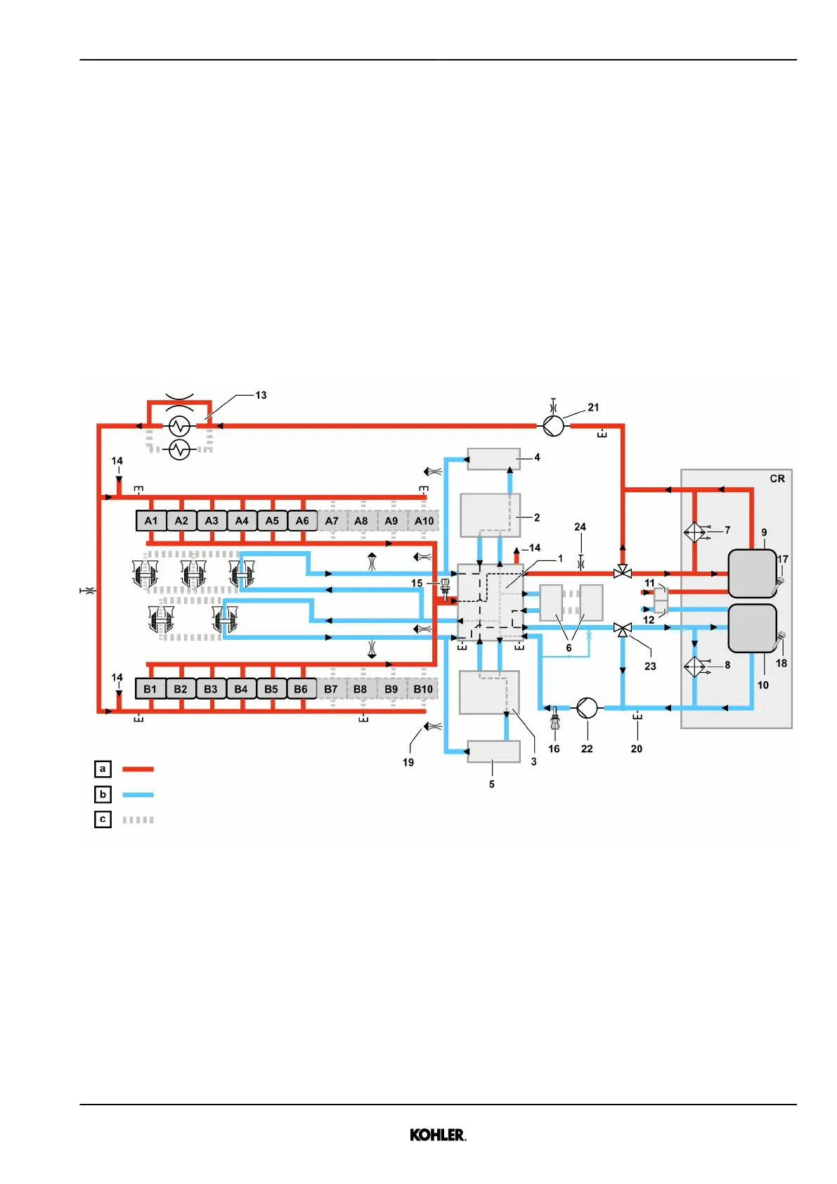
1.3.3 Cooling system
Coolant diagram
Fig. 23: Coolant diagram
a High temperature c Depending on engine config-
uration
b Low temperature CR Customer responsibility
1 Aggregate support 8 LT Water radiator 19 Venting point
2 Charge Air Cooler A 9 HT Expansion tank (including
ventilation line)
20 Drain point
3 Charge Air Cooler B 10 LT Expansion tank (including
ventilation line)
21 Coolant pump HT
4 Elbow A 11 Venting HT 22 Coolant pump LT
5 Elbow B 12 Venting LT 23 Mechanical thermostat
6 ECU 2-HD 13 Engine oil cooler 24 Manual venting point
See next page for continuation of the image legend
KD62V12 33525088601_7_1 EN_US
2021-07
© 2021 by Kohler Co. All rights reserved.
33
 Loading...