Product description Service and Repair Manual
Function description
Sensors list
17 B781 - Air intake pressure
switch - B side (clogging)
21 B703 - Charged air pressure
A after charge air cooler
Engine type Number of turbochargers TC1 TC2 TC3 TC4 TC5
V12 3 x x
V16 4 x x
V20 5 x x
Tab. 4: Blowby connections
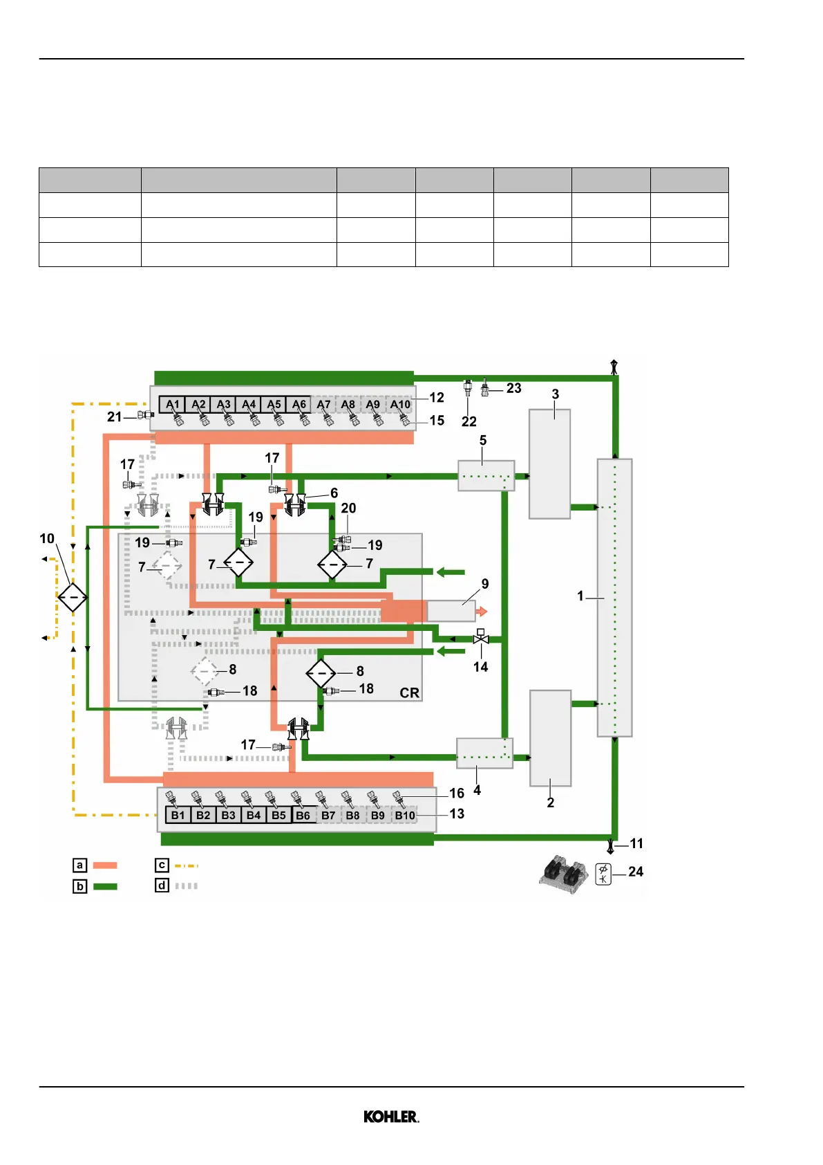
1.3.5 Charge air diagram (engine with EATS)
Fig. 26: Charge air diagram
a Exhaust gas c Oil vapor e For odd number of turbo-
chargers only
b Fresh air d Depending on engine config-
uration
CR Customer responsibility
1 Aggregate support 6 Turbocharger 11 Venting point
2 Charge air cooler - B side 7 Air filter - A side 12 Engine A bank
See next page for continuation of the image legend
36
© 2021 by Kohler Co. All rights reserved.
KD62V12 33525088601_7_1 EN_US
2021-07
 Loading...