11-98
140-3 SERIES
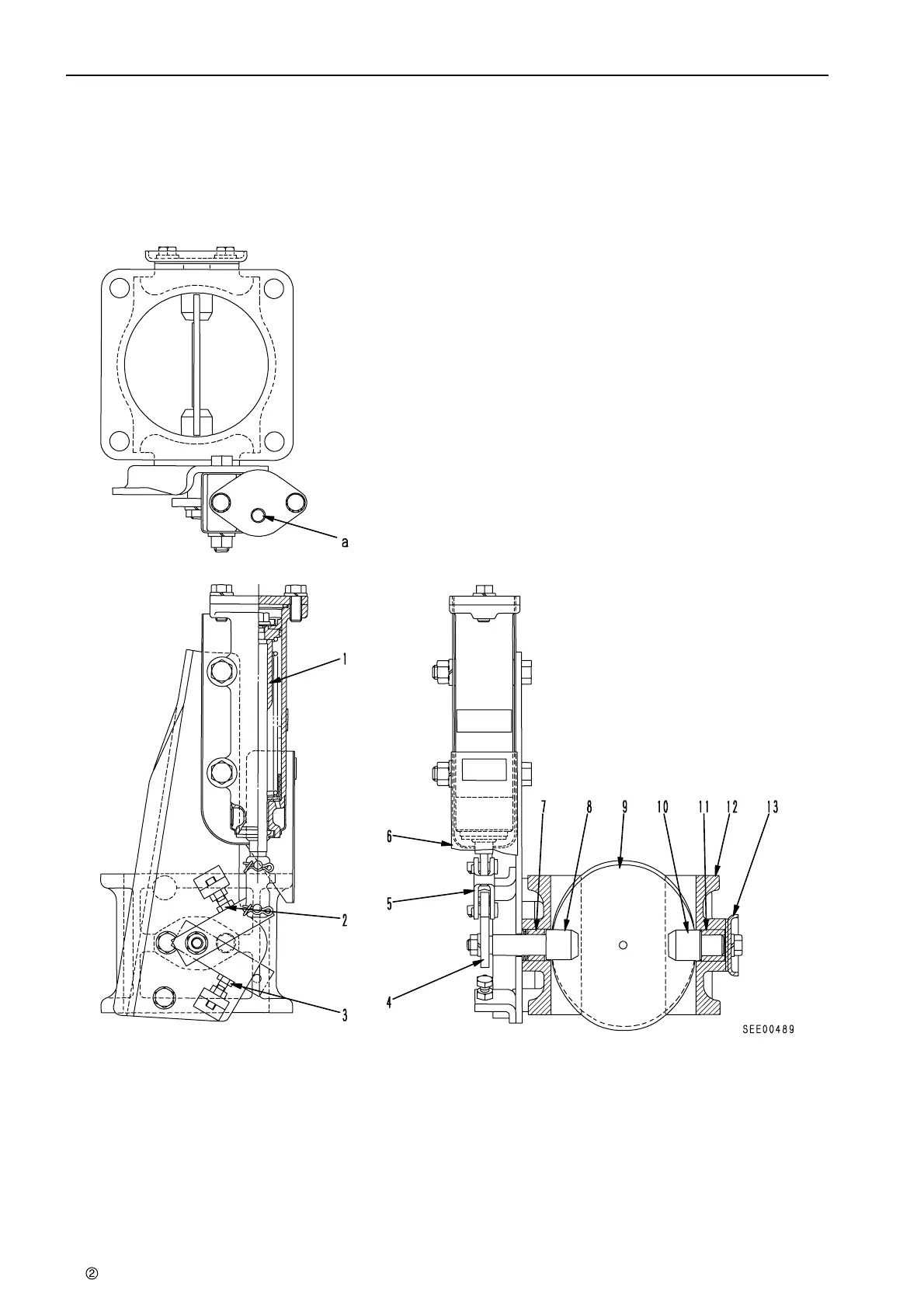
STRUCTURE AND FUNCTION, MAINTENANCE STANDARD EXHAUST BRAKE
EXHAUST BRAKE
SAA6D140E-3 (HD325-6)
BUTTERFLY VALVE TYPE
★ The shape may differ according to the machine
model.
1. Hydraulic cylinder 8. Spindle
2. Stopper bolt (fully open position) 9. Valve
3. Stopper bolt (fully closed position) 10. Spindle
4. Lever 11. Bushing
5. Yoke 12. Valve body
6. Insulator 13. Cover
7. Bushing
a. From exhaust brake valve
Outline
The exhaust brake is installed between the
engine turbocharger and muffler. It is actuated by
air pressure from the solenoid valve, and throttles
the exhaust passage from the turbocharger to the
muffler to reduce the speed of the engine.The
exhaust brake consists of the valve mechanism
and a hydraulic cylinder that operates the valve.
 Loading...

