12-18
140-3 SERIES
TESTING AND ADJUSTING TESTING AND ADJUSTING ALTERNATOR BELT TENSION
ADJUSTING SPEED SENSOR
ADJUSTING SPEED SENSOR
★ The G revolution sensor and NE revolution sen-
sor for the common rail type fuel injection system
cannot be adjusted.
★ Adjust the speed sensor as follows for the type
which uses an electronic system on the machine
and detects the signal from the flywheel ring
gear.
1.
Screw in sensor (1) until the tip contacts the tip of
the tooth of flywheel ring gear (2).
★ Check that there is no damage or metal pow-
der on the tip of the sensor when installing.
2
Thread:
Hydraulic sealant
2.
Turn sensor (1) back 1/2 – 2/3 turns.
★ This makes a clearance of 0.75 – 1.00 mm
between the tip of the sensor and the tip of
the gear tooth.
3.
Hold sensor (1) in position with nut (3).
3
Nut:
69 – 74 Nm {7.0 – 7.5 kgm}
TESTING AND ADJUSTING
ALTERNATOR BELT TENSION
1. Inspecting
Measure deflection
a
when the belt is pressed
with a finger at a point midway between the
alternator pulley and drive pulley.
★ Pushing force: Approx.98 Nm {approx.10 kg}
★ Deflection (one belt): 13 – 16 mm
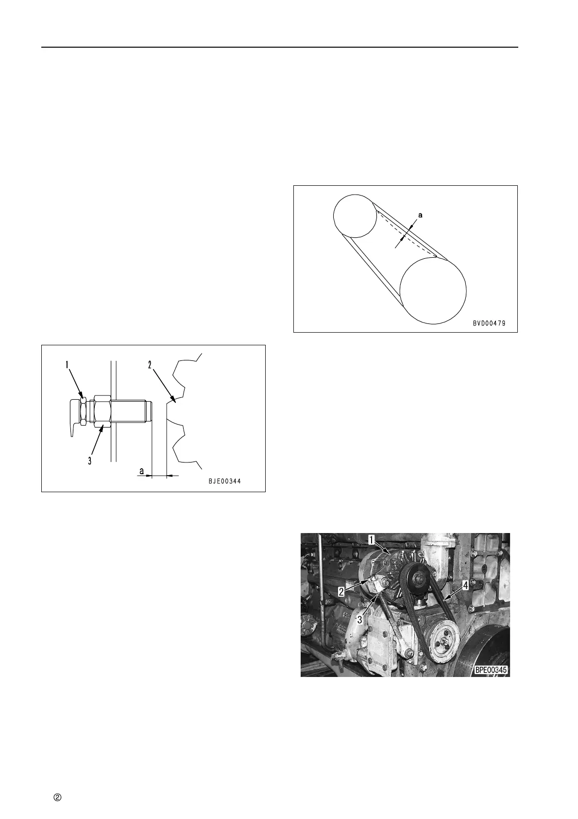
2. Adjusting
★ This makes a clearance of 0.75 – 1.00 mm
between the tip of the sensor and the tip of
the gear tooth.
★ If the deflection is not within the specified
range, adjust as follows.
1) Loosen 2 mounting bolts of alternator (1)
and 1 lock bolt of the bar.
2) Loosen locknut (2), move alternator (1) with
adjustment nut (3), and adjust the tension of
belt (4).
★ Deflection (one belt): 13 – 16 mm
3) Tighten locknut (2).
4) Tighten 2 mounting bolts of alternator (1)
and 1 lock bolt of the bar.
★ After adjusting, check the belt tension again.
 Loading...

