2-16
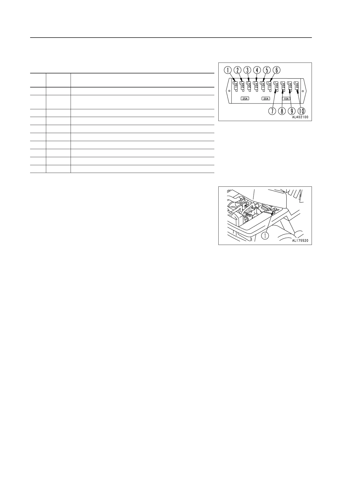
11.8.1 FUSE CAPACITY AND NAME OF CIRCUIT
11. EXPLANATION OF COMPONENTS 11. EXPLANATION OF COMPONENTS
Fuse
No
.
capacity
Name of circuit
1 10A F – R control
2 20A
Reverse lamp, Horn, Turn signal pilot lamp
Bucket positioner
3 30A Engine stop solenoid
4 25A Light switch
5 10A Monitor panel
6 10A Parking buzzer
7 20A Heater (front window)
8 25A Front wiper, Room lamp, Patrol light
9 20A Working lamp, Radio
0 20A Rear wiper
11.9 FUSIBLE LINK
If the power does not come on when the starting switch is turned
ON, the fusible link may be blown, so open the tilt hood at the rear
of the machine and check or replace it.
FUSIBLE LINK
65A: Chassis power source
REMARK
A fusible link is a large fuse wire installed in circuits where there
is a large amount of electricity flowing. In the same way as a normal
fuse, it acts to protect electrical component and wiring from burning
out if any abnormal current should flow.
 Loading...