3.1 Startup and shutdown
61
Chapter 3
AeroDR Interface Unit
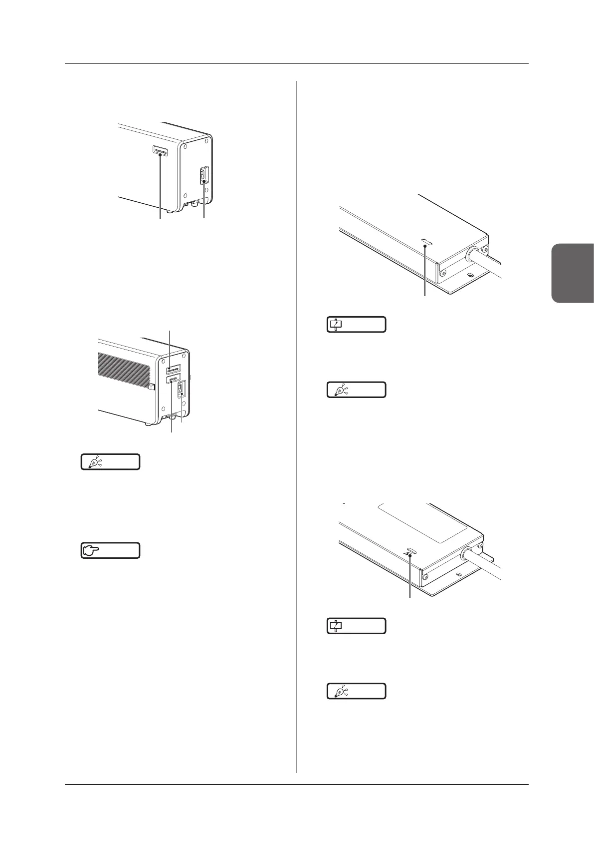
• Turn the power switch of the AeroDR Interface
Unit on, and conrm that the LED (green) lights.
Power switch
LED (green)
AeroDR Interface Unit2
• Turn the power switch of the AeroDR Interface
Unit2 on, and conrm that the Detector Connec-
tion LED (green) and Generator Interface LED
(green) light.
Power switch
Detector Connection LED (green)
Generator Interface LED (green)
HINT
•••••••••••••••••••••••••••••••••••••
• It takes time for the Generator Interface LED (green)
to light.
•••••••••••••••••••••••••••••••••••••••••••••••••••••
Hub
Reference
•••••••••••••••••••••••••••••••••••••
• When using a general-purpose hub, refer to its opera-
tion manual.
•••••••••••••••••••••••••••••••••••••••••••••••••••••
Detector Interface Unit
• When the power switch of the Power Sup-
ply Unit is turned on, power is supplied to the
Detector Interface Unit, and the LED (green) on
the Detector Interface Unit will light.
• When using the DI Unit AC Adapter, conrm that
the Detector Interface Unit is turned on when
the power plug is connected to a wall outlet and
the LED (green) lights.
LED (green)
IMPORTANT
•••••••••••••••••••••••••••••••••••••
• For power supply through PoE, supply the power from
the Power Supply Unit.
•••••••••••••••••••••••••••••••••••••••••••••••••••••
HINT
•••••••••••••••••••••••••••••••••••••
• When DR Detector is connected, the LED (blue) is on.
•••••••••••••••••••••••••••••••••••••••••••••••••••••
Detector Interface Unit 2
• When the power switch of the Power Sup-
ply Unit is turned on, power is supplied to the
Detector Interface Unit 2, and the LED (green)
on the Detector Interface Unit 2 will light.
LED (green)
IMPORTANT
•••••••••••••••••••••••••••••••••••••
• For power supply through PoE, supply the power from
the Power Supply Unit.
•••••••••••••••••••••••••••••••••••••••••••••••••••••
HINT
•••••••••••••••••••••••••••••••••••••
• When DR Detector is connected, the LED (blue) is on.
•••••••••••••••••••••••••••••••••••••••••••••••••••••
 Loading...