79PTO
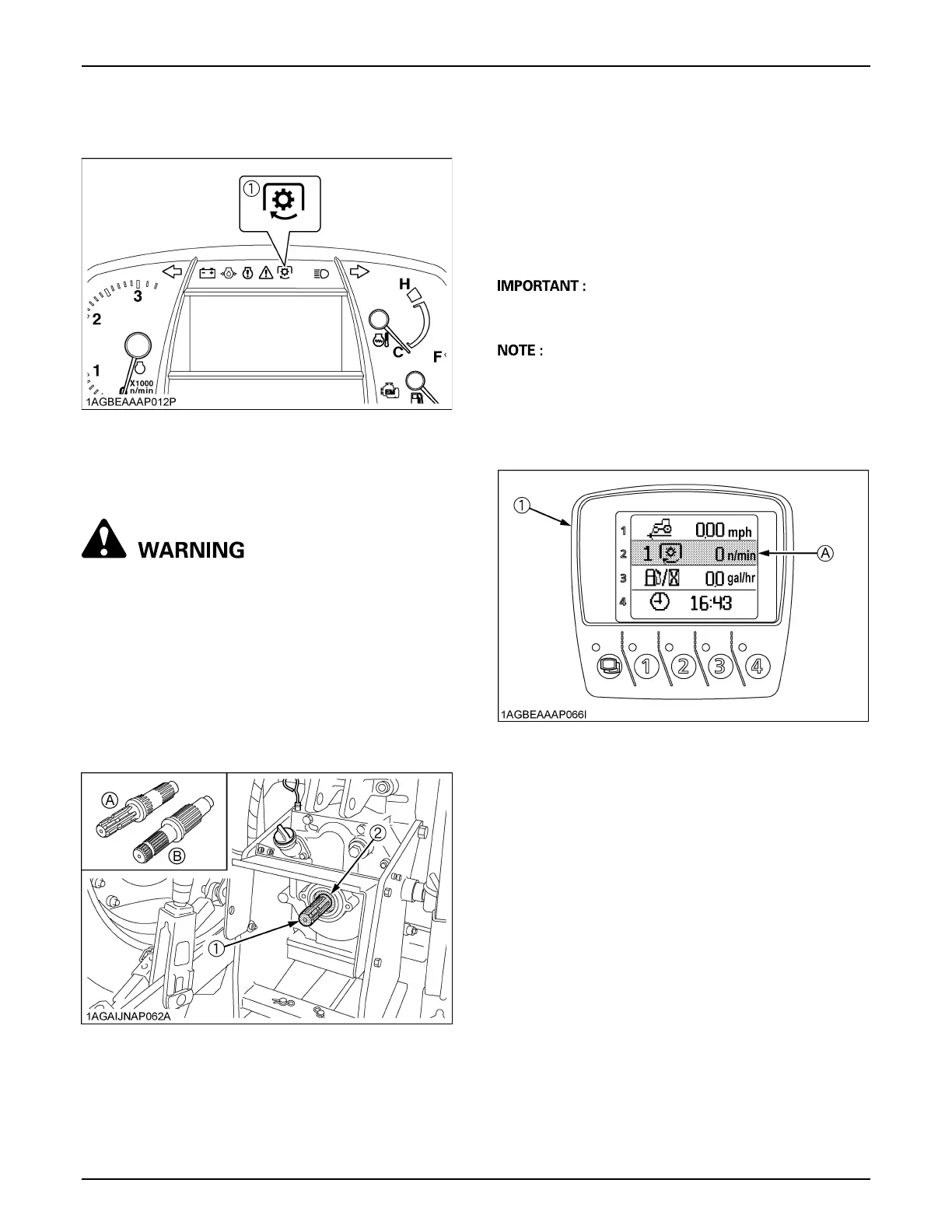
C PTO Clutch Indicator
The PTO clutch indicator turns on while PTO clutch
control switch is in "ON" (Engage) position.
B1000 rpm PTO Shaft
[if equipped]
To avoid personal injury or death:
A Be sure to observe the PTO shaft speed
prescribed for the individual implements. It is
extremely dangerous to run an implement at
high speed that is meant to be operated at low
speed. Use only when this higher rpm is
specifically recommended by the implement
manufacturer.
By interchanging the PTO shafts, 2 different PTO shaft
speeds can be obtained.
C PTO shaft interchanging procedure
1. The 6-spline 540 rpm PTO shaft is standard
equipment.
2. Place an oil pan under the PTO shaft to catch oil
spillage. Remove the snap ring, and then the PTO
shaft.
3. Install the 21-spline PTO shaft (1000 rpm). To ensure
that it is tight, push it in by turning.
4. Reinsert the snap ring.
A For maximum PTO shaft speeds of various
implements, see the implement Operator's Manual.
A Whenever the PTO speed is changed to the other
speed, it is necessary to switch the PTO speed display
mode of the side digital display. Otherwise the PTO
speed will not get correctly displayed in the side digital
display. (See "SIDE DIGITAL DISPLAY" in
"OPERATING THE TRACTOR" section.)
(1) PTO clutch indicator
(1) PTO shaft
(2) Snap ring
(A) 540 rpm PTO shaft
(B) 1000 rpm PTO shaft
(1) Side digital display (A) "PTO SPEED"
 Loading...