91HYDRAULIC UNIT
2. One-touch floating function
Set the mode selector switch to the "DRAFT" position.
Hold down the "LOWER" switch to keep the 3-point
hitch floating. This function is helpful in plowing, for
example. Release the switch and the 3-point hitch
returns to the draft control position.
3. "RAISE" and "LOWER" operation with the 3-point
hitch going halfway
(1) When the "LOWER" switch is pressed with the 3-
point hitch going up halfway, the 3-point hitch
stops at this position. (The indicator turns on.) Re-
push the "RAISE" or "LOWER" switch, and the 3-
point hitch will go up or down respectively.
(2) To lower the 3-point hitch with the 3-point hitch
going up halfway, hold down the "LOWER" switch
for 2 seconds or push it twice.
(3) When the "RAISE" switch is pressed with the 3-
point hitch going down halfway, the 3-point hitch
goes up.
B3-Point Hitch's Position Lock
C Position Lock
If any of the following actions are made with the hydraulic
control lever and the lower links at different heights, the
position lock is activated. The 3-point hitch control is
interrupted and the 3-P. Lifting / Lowering indicator starts
flashing (2 or so flashes every second).
1. Starting the engine.
2. Activating the 3-P. Remote hitch Up / Down switch.
3. Changing the mode selector switch.
C Releasing the position lock
If applied, press the 3-P. Quick Raise switch or 3-P. Quick
Lower switch.
A When the position lock is released with the 3-P. Quick
Raise / Lower switches, the 3-point hitch goes up or
down.
REMOTE HYDRAULIC CONTROL SYSTEM
The hydraulic auxiliary control valves can be installed up
to quartet segments.
BRemote Control Valve
There are 2 types of remote valves available for these
models.
A Double acting valve with detents and self cancelling:
This valve may be placed in the detent mode. The
lever will stay in this position until the pressure reaches
a predetermined level or a cylinder reaches the end of
its stroke. Then it will automatically return to neutral
A Double acting valve with float position:
This valve may be placed in the float mode with the
control lever all the way forward. The cylinder is free to
extend or retract, letting an implement such as a
loader bucket follow the ground.
BRemote Control Valve Lever
The remote control valve lever directs pressurized oil flow
to the implement hydraulic system.
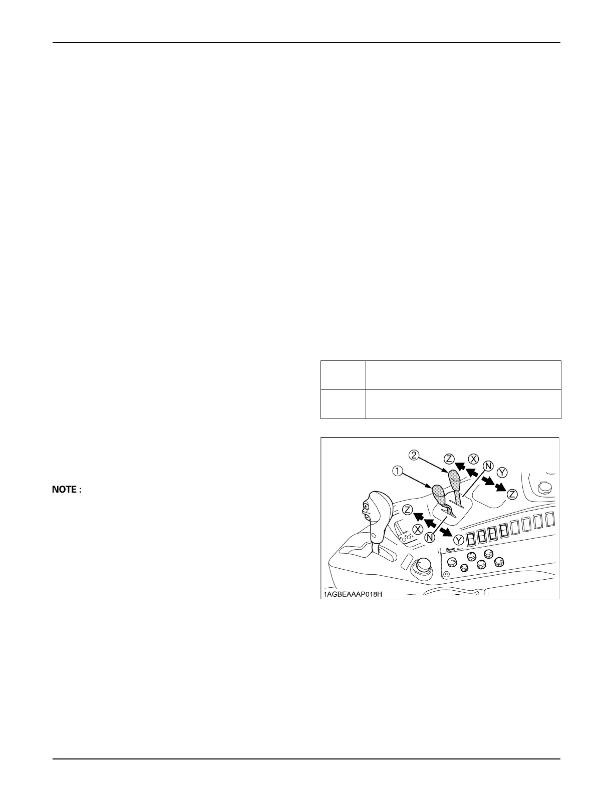
[Example: Installing double segment valves]
1st
Double acting valve with float position
(standard)
2nd
Double acting valve with detents and self
cancelling (standard)
(1) Remote control valve lever 1
(2) Remote control valve lever 2
 Loading...