7-M1
F2880, F3680, RCK72-F36, RCK72R-F36, RCK60-F36, RCK60R-F36, WSM
HYDRAULIC SYSTEM
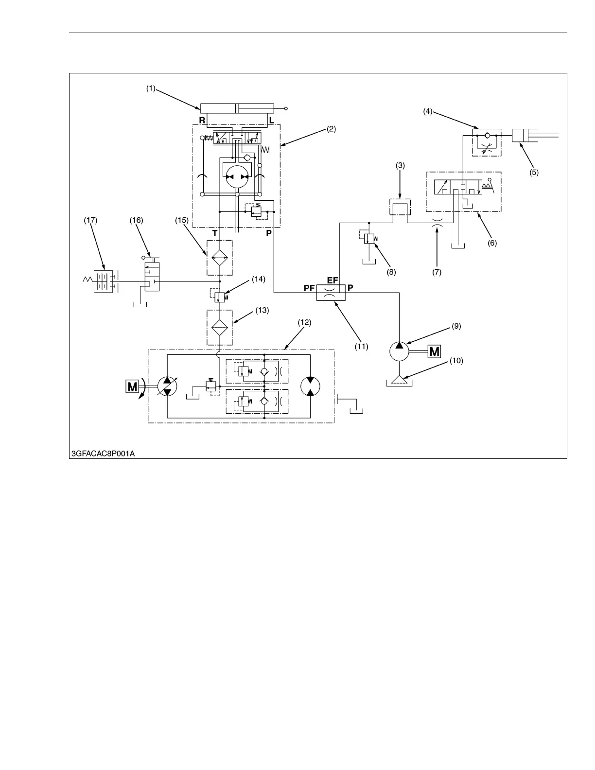
1. HYDRAULIC CIRCUIT
The hydraulic system of these machines are composed of a hydraulic pump (9), hydraulic block type outlet (3),
implement control valve (6), hydraulic cylinder (5) and other components.
This system has the following functions.
Position control of the front implement connected to the lift arm.
Hydraulic power take off from the hydraulic block type outlet (3) to operate the implements such as a grass collector
and, etc..
Oil is supplied by a hydraulic pump (9) connected to the engine. When an engine is started, hydraulic pump (9)
starts running, sucks oil from a transmission case. The hydraulic pump (9) forces out the oil to the hydraulic block
type outlet (3), implement control valve (6), hydraulic cylinder (5), steering controller (2), PTO control valve (16),
hydraulic PTO clutch (17) and hydrostatic transmission (12).
(1) Steering Cylinder
(2) Steering Controller
(3) Hydraulic Block Type Outlet
(4) Lowering Speed Adjusting
Valve
(5) Hydraulic Cylinder
(6) Implement Control Valve
(7) Orifice
(8) Relief Valve
(9) Hydraulic Pump
(10) Oil Strainer
(11) Flow Priority Valve
(12) Hydraulic Transmission
(13) Filter Cartridge
(14) PTO Charge Relief Valve
(15) Oil Cooler
(16) PTO Control Valve
(17) Hydraulic PTO Clutch
EF :EF Port
PF :PF Port
P : P Port
T : T Port
L : L Port
R : R Port
 Loading...