2-M16
F2880, F3680, RCK72-F36, RCK72R-F36, RCK60-F36, RCK60R-F36, WSM
TRANSMISSION
5. PTO SECTION
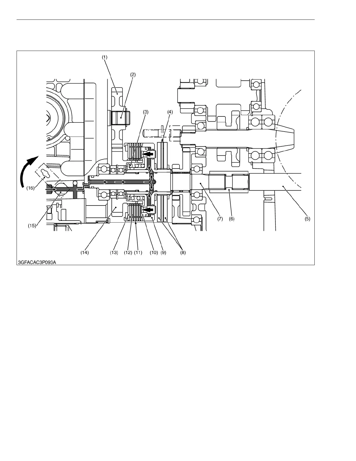
■ PTO “Engage”
The main components of the PTO section are shown in the figure above.
When the PTO lever is set to “ENGAGE” position, the PTO control rod is pulled and the PTO control valve (15)
rotates.
The oil is forced out by the hydraulic pump to the hydraulic PTO clutch through the steering controller, PTO control
valve (15) and clutch shaft (7).
The piston (10) is pushed against the steel plates (11), clutch discs (12) and pressure plate (13) by this movement.
The steel plates (11) and pressure plate (13) are held between the clutch discs (12) and piston (10), and the friction
between them cause the clutch discs (12) to rotate, thus transmitting the power from the engine to the implement as
follows ;
Pump Shaft (2) → 28T Gear (1) → 33T Gear (13) → Piston (10) → Clutch Case (9) → Clutch Shaft (7) → Coupling
(6) → PTO Shaft (5).
(1) 28T Gear
(2) Pump Shaft
(3) Return Spring
(4) PTO Brake Disc
(5) PTO Shaft
(6) Coupling
(7) Clutch Shaft
(8) PTO Brake Plate
(9) Clutch Case
(10) Piston
(11) Steel Plate
(12) Clutch Disc
(13) Pressure Plate
(14) 33T Gear
(15) PTO Control Valve
(15) Valve Lever
 Loading...