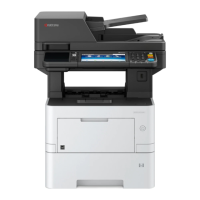
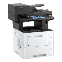
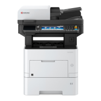
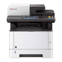
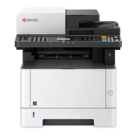
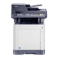
2NM/2NX/2NY/2NZ/2P0/2P6
2-2 Operation of the PWBs
2-2-1 Upgrading the firmware ......................................................................................................... 2-2-1
2-2-2 Control PWB (CONPWB) ...................................................................................................... 2-2-3
(1) Connector position............................................................................................................ 2-2-3
(2) PWB photograph ..............................................................................................................2-2-3
(3) Connector lists.................................................................................................................. 2-2-4
(4) Detaching and refitting the PWB. (CONPWB)................................................................ 2-2-12
(5) Remarks on Control PWB replacement.......................................................................... 2-2-15
2-2-3 Connect Left PWB (CLPWB) ............................................................................................... 2-2-17
(1) Connector position.......................................................................................................... 2-2-17
(2) PWB photograph ............................................................................................................ 2-2-17
(3) Connector lists................................................................................................................ 2-2-18
(4) Detaching and refitting the PWB. (C-LPWB) .................................................................. 2-2-20
2-2-4 Connect Right PWB (CRPWB)............................................................................................ 2-2-27
(1) Connector position.......................................................................................................... 2-2-27
(2) PWB photograph ............................................................................................................ 2-2-27
(3) Connector lists................................................................................................................ 2-2-28
(4) Detaching and refitting the PWB. (CRPWB)................................................................... 2-2-31
2-2-5 High Voltage PWB (HVPWB) .............................................................................................. 2-2-34
(1) Connector position.......................................................................................................... 2-2-34
(2) PWB photograph ............................................................................................................ 2-2-34
(3) Connector lists................................................................................................................ 2-2-35
(4) Detaching and refitting the PWB. (HVPWB)................................................................... 2-2-36
2-2-6 Power source PWB (PSPWB) ............................................................................................. 2-2-46
(1) Connector position.......................................................................................................... 2-2-46
(2) PWB photograph ............................................................................................................ 2-2-46
(3) Connector lists................................................................................................................ 2-2-47
(4) Detaching and refitting the PWB. (PSPWB) ................................................................... 2-2-48
2-2-7 Operation panel PWB (OPPWB) for HyPAS model............................................................. 2-2-52
(1) Connector position.......................................................................................................... 2-2-52
(2) PWB photograph ............................................................................................................ 2-2-52
(3) Connector lists................................................................................................................ 2-2-53
(4) Detaching and refitting the PWB. (OPPWB)................................................................... 2-2-56
2-2-8 Operation panel PWB (OPPWB) for Basic model ............................................................... 2-2-58
(1) Connector position.......................................................................................................... 2-2-58
(2) PWB photograph ............................................................................................................ 2-2-58
(3) Connector lists................................................................................................................ 2-2-59
(4) Detaching and refitting the PWB. (OPPWB)................................................................... 2-2-60
2-3 Appendixes
2-3-1 Appendixes ............................................................................................................................ 2-3-1
(1) List of maintenance parts ................................................................................................. 2-3-1
(2) Maintenance kits...............................................................................................................2-3-2
(2-1) 40 ppm model.......................................................................................................... 2-3-2
(2-2) 50/60 ppm model..................................................................................................... 2-3-2
(2-3) For DP ..................................................................................................................... 2-3-2
(3) Repetitive defects gauge .................................................................................................. 2-3-3
(4) Firmware environment commands ................................................................................... 2-3-4
(5) Chart of image adjustment procedures .......................................................................... 2-3-13
(6) Wiring diagram (40 ppm (LED model))........................................................................... 2-3-16
(7) Wiring diagram (40 ppm (HyPAS model)) ...................................................................... 2-3-19
(8) Wiring diagram (50/60 ppm (HyPAS model)) ................................................................. 2-3-22
 Loading...
