208
8 CO/O
2
Control
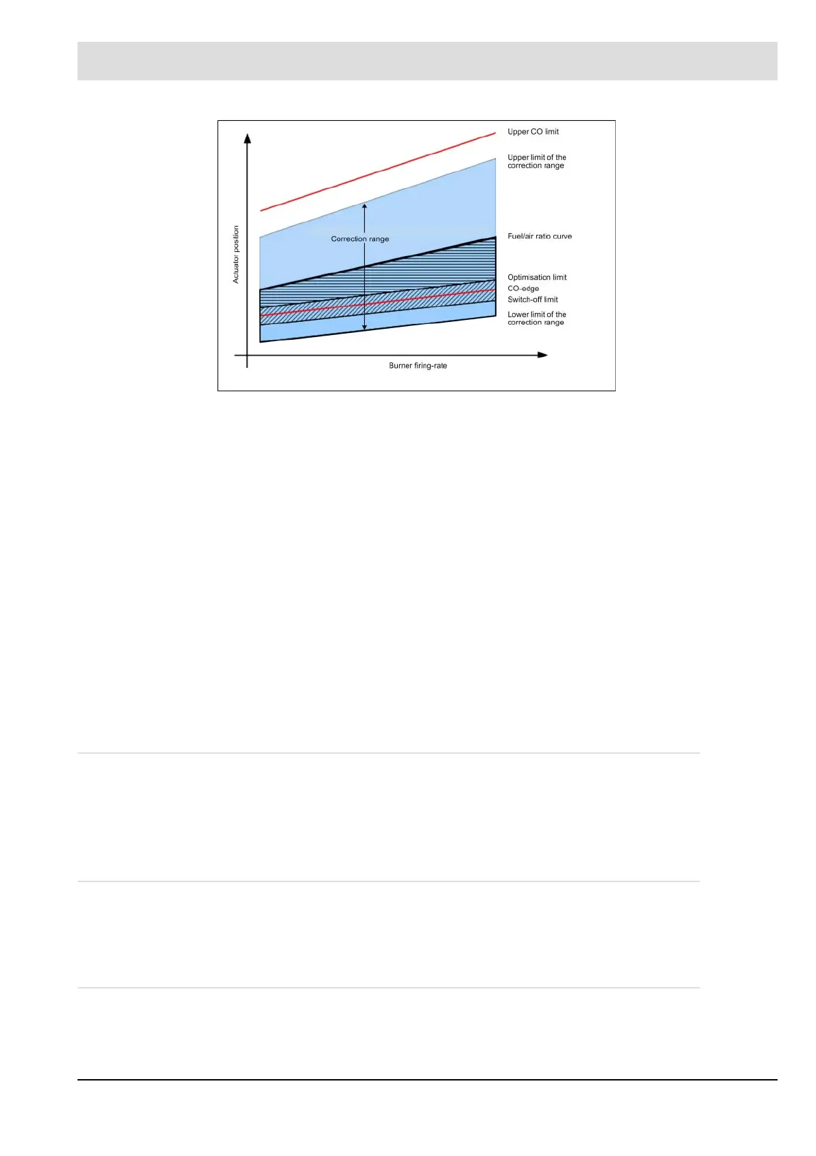
Fig. 8-1 Correction range of the CO controller
The upper limit of the correction range ensures that all errors leading to a movement of the
controller in the direction of excess air only move the actuating devices up to an upper limit
that is still safe.
If this upper limit is exceeded in spite of this, and the correction range is violated, the controller
recognises this problem.
In contrast, errors that lead to the CO controller regulating in the direction of a lack of air must
be detected beforehand.
To handle this error, two additional monitors are implemented, which detect in a variety of
ways by means of the O
2
and CO sensor when the exhaust gas falls below a critical O
2
min-
imum value or exceeds a CO
e
value (O
2
minimum monitor /U-CO
e
maximum monitor).
A "CO
e
dynamics test" and "O
2
dynamics test" ensure that these monitors are working cor-
rectly. These tests check whether the probes still react to changes of the fuel-air mixture by
means of a short modification of the exhaust gas composition.
Monitors for limit values have a timeout of < 20 s (<0.4 % O
2
). This is due to the long running
time of the exhaust gas flow from the burner to the exhaust gas sensor system and the thus
very slow control function.
8.3 Requirements
To use CO/O
2
control, one of the following systems must be implemented:
• LT3-F in combination with KS1D
• LT1/LT2 for O
2
measurement in combination with LT2 and KS1D
8.4 Required Inputs/Outputs
• Corrections to the electronic ratio control
• Sensor input to LT3
8.5 Required Parameters
All parameter groups for CO controller and CO monitoring are required for CO/O
2
control.

 Loading...
