246
8 CO/O
2
Control
8.11.3 CO Controller Faults
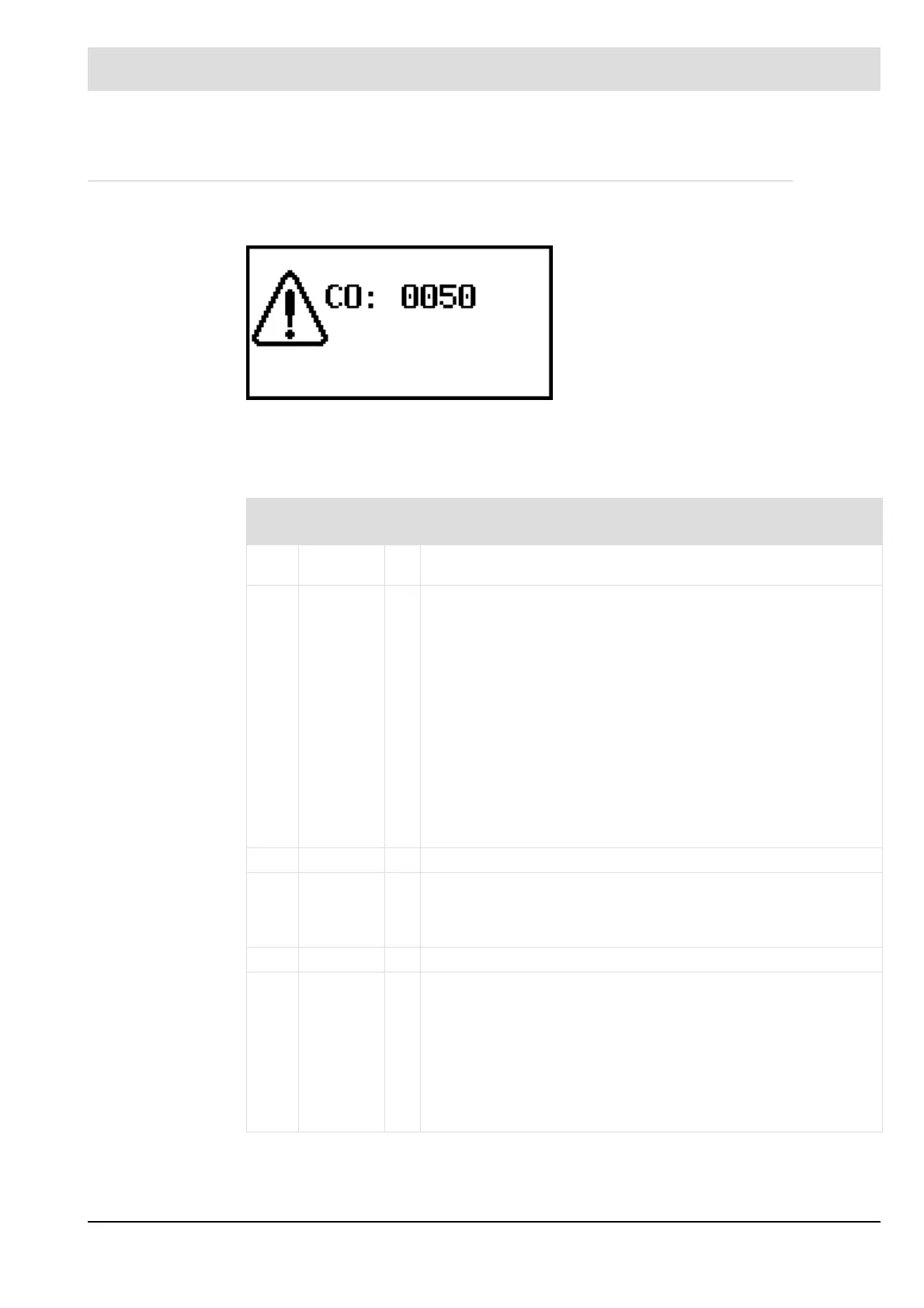
CO fault example:
When the following monitoring routines are activated, CO control is deactivated. Depending
on the settings made, CO optimisation is completely deactivated (factory setting) or switched
to O
2
trim online.
Fig. 8-39 Display of a CO monitoring fault
The plausibility check of the sensor voltage
of the CO
e
measuring cell with O
2
trim has
been activated.
No. Fault/
information
Comment
0040 CO fault
ot
There is no CO edge information available on the LAMTEC SYSTEM
BUS.
Lambda Transmitter is incorrectly configured or not connected to LSB.
LSB connection is twisted.
(see chapter 8.8 Electrical Connection - Connection via LSB)
Lambda Transmitter is not in measuring mode (malfunction/cold start).
Lambda Transmitter is in adjustment mode.
The correction range is set too small. As a result, the control
cannot approach the CO edge.
– Check correction range (P703) and adjust if necessary.
The electronic ratio curve is set in such a way that the CO edge cannot
be reached.
– Check curve setting and adjust l if necessary.
With CO, the LT does not achieve the necessary probe dynamics for
triggering the CO edge.
– Check the trigger threshold for the edge signal in the LT and
adjust it if necessary.
0041 CO fault
ot
CO probe voltage is outside the monitoring window (U
CO/H2
).
Incorrect polarity of probe connection (signal).
The probe is defective.
Permissible probe voltage range in Lambda Transmitter is too small.
Range: +10 ... + 500 mV
0042 CO fault
ot
CO probe offset is outside the monitoring window.
During the offset calibration process 21 % O2 (air) were not present at
the measuring point.
– Repeat offset calibration
The probe heats up.
– Check internal probe resistance Ri in LT
– Check wiring and correct if necessary
The probe is defective.
Fault in the wiring (incorrect polarity)
Range: -25 ... +10 mV/20 s

 Loading...
