279
12 Appendix
12.2 Acceptance and Inspection
NOTICE
The following table on system acceptance is only an example and does not imply complete-
ness. Local regulations or special configurations may require further testing or may not require
listed testing.
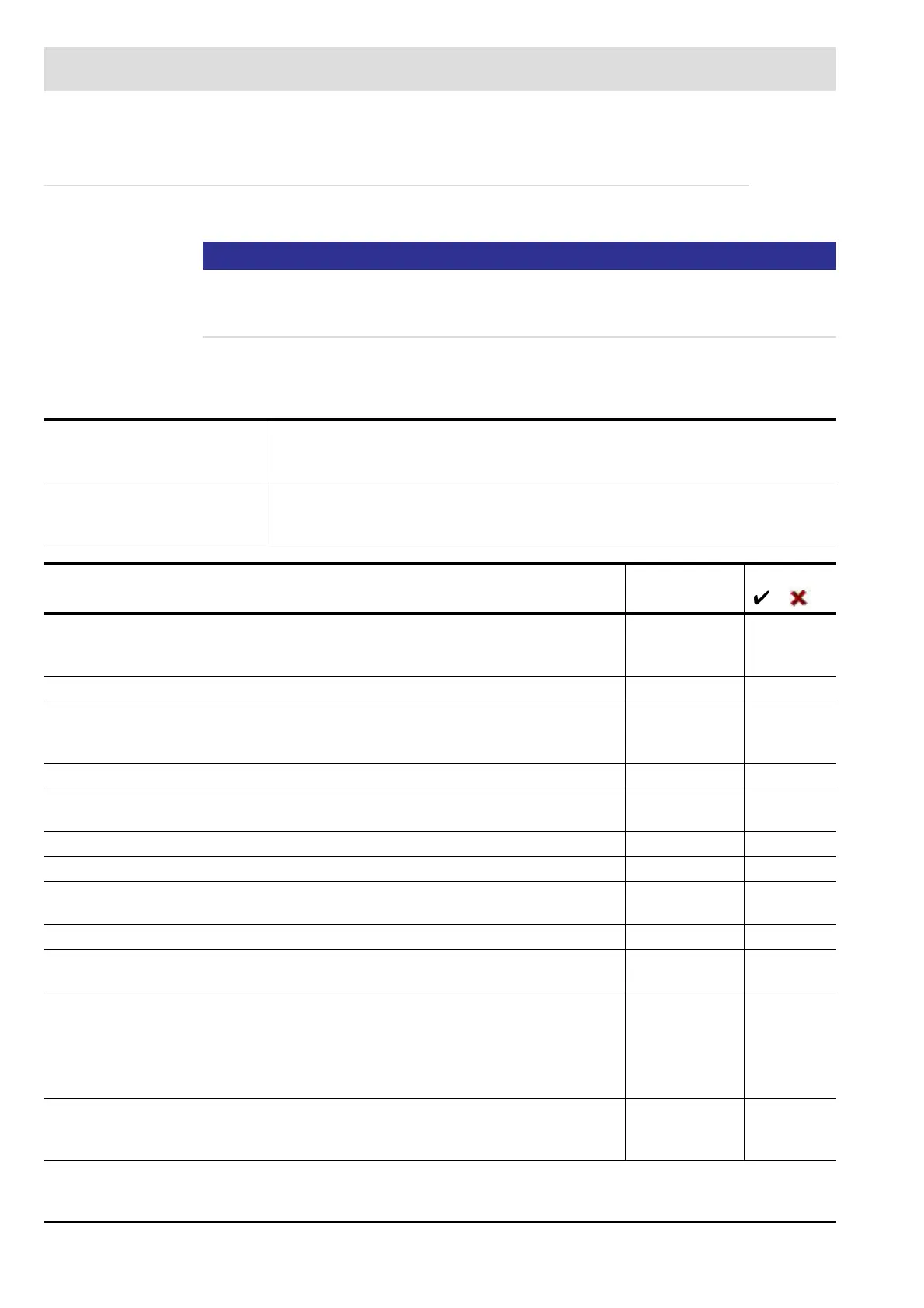
Table on system acceptance
The following table must be completed when completing the commissioning process.
Tools,
equipment
incl. calibration data
Configuration of test object
Hardware version
Software version
Test description Date/Tester Result
/
Extra low voltage conductors are correctly laid so that they are not positioned in
one channel together with the supply and outgoing conductors from the power
electronic board.
For conductor lengths <10m, shielded cable is used.
When using an insulation electrode, ensure the reinforced insulation of the con-
necting pipework in accordance with DIN EN 601730-2-5 section 20 (protection
against contact).
All electrical plug-in connections have been checked.
The current software version number and all CRCs for the user levels has been
documented.
The plant has at least IP40 contact protection indoors and IP54 outdoors.
For access level 1, a password not equal to 00000 has been entered.
All security relevant parameters for each function to be monitored have been set in
accordance with the standards that apply to the plant.
The actuators conform to the approved types.
*
In SETTING mode, the actuators can be traversed manually across the entire set-
ting range.
The switch-off tests of the LAMTEC FFS07/FFS08 flame sensor have been cor-
rectly
performed.
Information on the switch-off tests e.g. for flame scanners from other manufactur-
ers, see manufacturer's documentation.
The setting values for the actuators to control the fuel quantity, air quantity, recircu-
lation gas quantity and all other, safety-relevant actuating combustion variables
are stored in sufficient numbers across the performance range of the burner.

 Loading...
