Development Kit
In addition to the status LEDs on the XPort™, the evaluation board contains multiple LEDs.
A red LED is driven by the power supply. The remaining LEDs are driven by the PLD and in
the basic mode of operation, indicate whether the RS232 interface is valid, the serial
interface transmit data is active, the serial interface receive data is active, and the state of
the three configurable pins CP1, CP2, and CP3.
The PLD and a 6-position DIP switch control the Evaluation Board mode of operation. The
switch outputs are used as inputs to the PLD to select the desired mode of operation.
TP8 TP9
XPort
DIP
SWITCH
RESET
+5
VDC
IN
3.3V
POWER
PIO
RS232
PLD
TMR
LEDs
SLOW
PWR
LED
RTS, DCD
DTR, CTS
PLD HEADER
RXD/TXD
SWITCH
RESET
PADS
JP3
JP4
J1
D2
SW1SW2
DB-9F
TP13
TP11
RTS
DTR
CTS/DCD
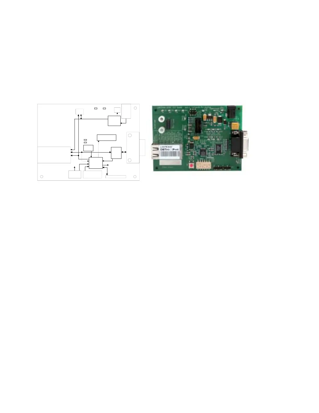
Figure 2-1 - Evaluation Board Block Diagram
2.1.1 Major Components
The major components of the evaluation board include:
! RS232 Transceiver
! Universal Power Adapter
! Reset Switch
! DIP Switch
! DB-9 Interface Connector
! Test points to monitor all XPort™ pins.
! 6 pin header (JP4) for connecting user devices or circuits to CP1, CP2, and CP3.
! Power, signal ground, and reset inputs are also available on JP4.
2-2 XPort™ User Manual and Development Kit
 Loading...