Development Kit
2.6.3 SW1-4, SW1-5 Options
SW1-5 controls the routing of the CP3 (Configurable Pin 3) signal from the XPort™. CP3 is
connected to pin 8 of the XPort™ and can be software configured as RTS, LED3, DTR, IN3,
or OUT3. With SW1-5 in the OFF position, the CP3 signal is routed to SW1-4.
SW1-4 and SW1-5 are inputs to the PLD which does the actual switching. The drawings
represent the logical switching functions.
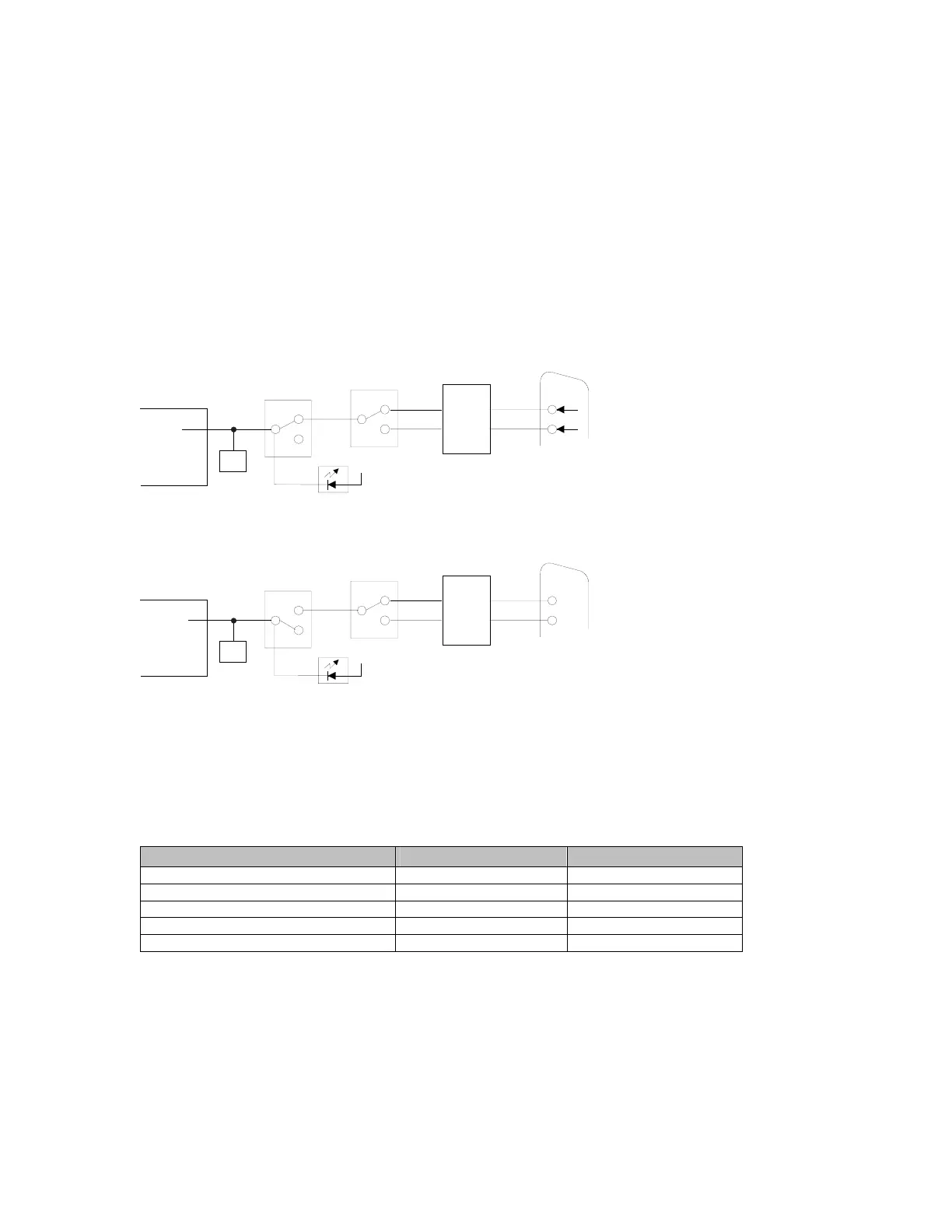
CP3 options are a little more complicated because both SW1-4 and SW1-5 are used in the
configuration setup. In this drawing, SW1-5 is OFF, which connects XPort™ pin-8 to the
RS232 transceiver. The XPort™ Configurable Pin 3 (CP3) is configured for RTS. SW1-4 is
ON, which will route the signal from XPort™ pin-8 to P1 pin-7 (RTS).
8
MAX232
DB-9
P1
7RTS
RS232
TTL
4DTR
CP3
RTS
LED3
DTR
IN3
OUT3
SW1-4
PLD
OFF
ON
SW1-5
PLD
OFF
ON
XPort
JP4 - PIO
HEADER
6
CP3 LED
3.3v
In the next drawing, SW1-5 is ON, which disconnects XPort™ pin-8 from reaching the
RS232 transceiver. The XPort™ Configurable Pin 3 (CP3) is configured for LED3.
8
MAX232
DB-9
P1
7RTS
RS232
TTL
4DTR
CP3
LED3
RTS
DTR
IN3
OUT3
SW1-4
PLD
OFF
ON
SW1-5
PLD
OFF
ON
XPort
JP4 - PIO
HEADER
6
CP3 LED
3.3v
When Configurable Pin 3 is configured for LED3, it functions as a diagnostic indicator. The
LED3 signal in combination with the LED1 signal will indicate diagnostic information as
shown in the following table.
Note: CP1 must be configured for LED1 and CP3 must be configured for LED 3 for
diagnostic mode.
Table 7 - LED States
Condition
CP3 LED (LED3) CP1 LED (LED1)
No Errors OFF ON
Network controller error ON Blink 3x / 4 sec OFF
Duplicate IP address present ON Blink 5x / 4 sec OFF
No DHCP response Blink 2x /sec Blink 5x / 4 sec OFF
Setup menu active Blink 2x / sec See Note
Note: During a Telnet connection, CP1 LED (LED1) will be ON. For a serial port connection,
CP1 LED (LED 1) is blinking for 2 sec, then OFF for two seconds. (It appears as 4 blinks,
then OFF for 2 seconds)
CTS and RTS work together for hardware flow control. Configurable Pin 3 (CP3) should be
configured as RTS when Configurable Pin 1 (CP1) is configured as CTS. Select hardware
flow control as described in Flow on page 4-12.
See OEM Configurable Pins on page 6-13 for configuring CP3 as IN3 or OUT3.
XPort™ User Manual and Development Kit 2-7
 Loading...