Development Kit
2.6.2 SW1-3 Options
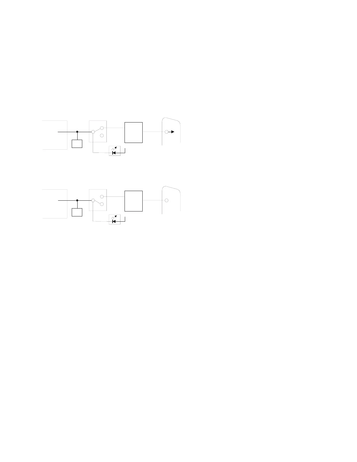
SW1-3 controls the routing of the CP2 (Configurable Pin 2) signal from the XPort™. CP2 is
connected to pin 7 of the XPort™ and can be software configured as DCD, IN2, or OUT2.
SW1-3 is an input to the PLD which does the actual switching. The drawings represent the
logical switching function.
In this drawing, SW1-3 is OFF, which connects XPort™ pin-7 to the RS232 transceiver. The
XPort™ Configurable Pin 2 (CP2) is configured for DCD.
7
DB-9
P1
1DCD
CP2
DCD
IN2
OUT2
MAX232
RS232
SW1-3
PLD
OFF
ON
XPort
CP2 LED
3.3v
JP4 - PIO
HEADER
2
In this drawing, SW1-3 is ON, which disconnects XPort™ pin-7 from the RS232 transceiver.
The XPort™ Configurable Pin 2 (CP2) is configured for OUT2.
OUT2
IN2
DCD
7
DB-9
P1
1DCD
CP2
MAX232
RS232
SW1-3
PLD
OFF
ON
XPort
CP2 LED
3.3v
JP4 - PIO
HEADER
2
See OEM Configurable Pins on page 6-13 for configuring CP2 as IN2 or OUT2.
2-6 XPort™ User Manual and Development Kit
 Loading...