8: Channel Mode: Channel Configuration
XPress™ DR Industrial Device Server User Guide 49
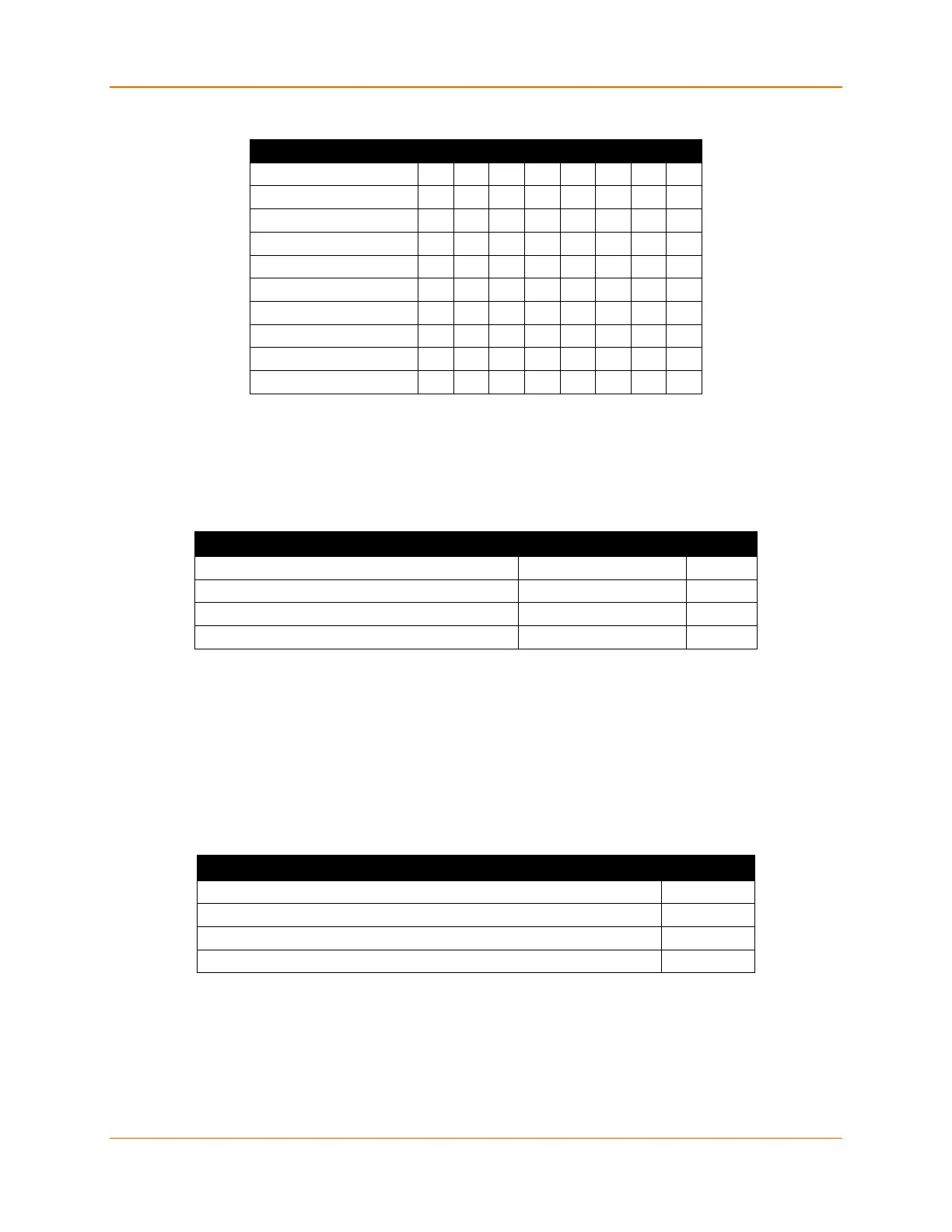
Table 8-1 Interface Mode Options
RS-232C
0 0
RS-422/485
0 1
RS-485 2-wire
1 1
7 Bit 1 0
8 Bit 1 1
No Parity 0 0
Even Parity 1 1
Odd Parity 0 1
1 Stop bit 0 1
2 Stop bit 1 1
(1) The XPress DR requires you to choose the correct setting in the IF mode, and to also set the
front-panel switch for selection of RS-232/RS-485.
The following table demonstrates how to build some common Interface Mode settings:
Table 8-2 Common Interface Mode Settings
Common I/F Mode Setting Binary Hex
RS-232C, 8-bit, No Parity, 1 stop bit (1) 0100 1100 4C
RS-232C, 7-bit, Even Parity, 1 stop bit (1) 0111 1000 78
RS-485 2-Wire, 8-bit, No Parity, 1 stop bit (1) 0100 1111 4F
RS-422, 8-bit, Odd Parity, 1 stop bit (1) 0101 1101 5D
(1) The XPress DR requires you to choose the correct setting in the IF mode, and to also set the
front-panel switch for selection of RS-232/RS-485.
Flow
Flow control sets the local handshake method for stopping serial input/output.
Flow (00) ? _
Table 8-3 Flow Control Options
Flow Control Option Hex
No flow control 00
XON/XOFF flow control 01
Hardware handshake with RTS/CTS lines 02
XON/XOFF pass characters to host 05
 Loading...