1 2
POWER
– +
R1
R2
R3
R4
F1
F2
F3
F4
F5
F6
F7
F8
GND
12V
+
–
SOS
+
–
LOCK
To SOS button
To IU 2
To IU 3
To IU 4
Sub System OUT
1 2 3 4
POW ER
+
-
B DCA
+
– –
+
Electronic lock
SENSOR
GND 12V F1
SENSOR
GND 12V F8
ALARM SENSORS
323015
Small EP
Handset
Normally a standard 0.5 mm
2
cable can be used
(depending on sensor type and installation distance)
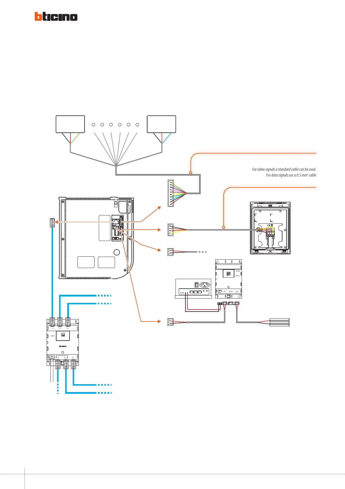
For video signals a standard cable can be used.
For data signals use a 0.5 mm
2
cable
(in accordance with installation distances)
Adaptor 15 V/2 A
323002
Diagram 1
iu wired connection + alarm connection
96
WIRING DIAGRAMS - VARIANTS

 Loading...