F F I I #I #I
F F I I #I #I
F F I I #I #I
F F I I #I #I
B DCA
+
– –
+
BUS
1 2
BUSBUS
BUS BUS
F F I I #I #I
F F I I #I #I
F F I I #I #I
F F I I #I #I
1 2
BUSBUS
BUS BUS
321070 321070
321070 321070
321070 321070
321070 321070
323002
323002
323005
322011
x x 0 1 x x 0 4
x x 0 2 x x 0 3
0 1 0 1 0 1 0 4
0 1 0 2 0 1 0 3
L + +12L – UNLOCK
PBL1
LAN SYSTEM1
SYSTEM2
WEP
DCV OUT GAIN
Speed Full Link Aux System
323011
323011
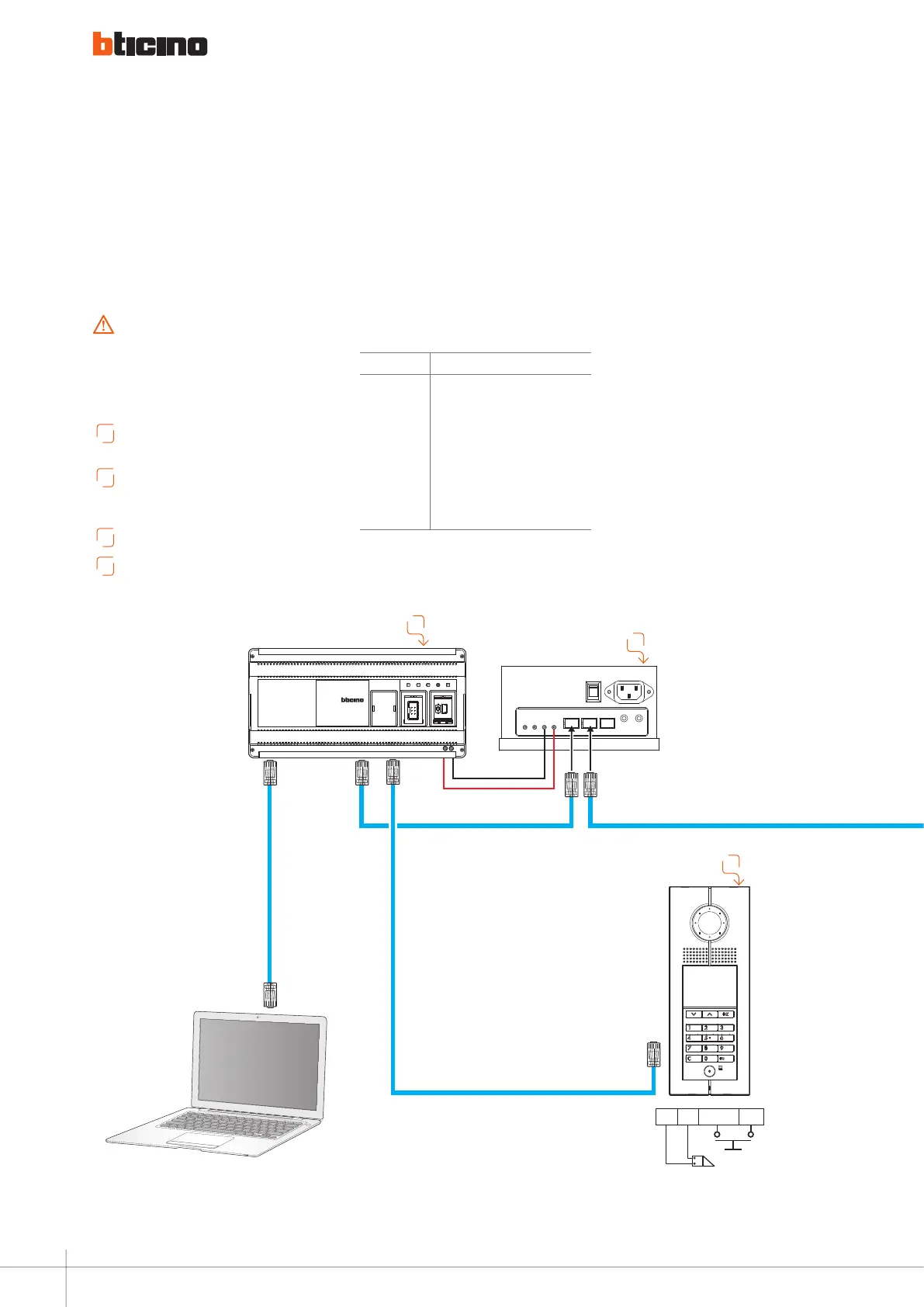
Diagram 8
A
To install alternative internal units, refer to
wiring variant section.
B
To install alternative Entrance panel, refer to
wiring variant section.
Device configuration by SF2 software..
C
Set internal IMPEDANCE SWITCH to ON.
D
Physical configuration or advanced configuration by
software MHSUITE.
Configure and insert the jumpers with the system
SWITCHED OFF. Also every time the configuration is
modified the pws must be switched OFF and ON again,
waiting about 1 minute.
WARNINGS:
ITEM DEscrIPTION
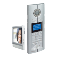
322011
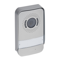
Digital call entrance panel
323011 D45/IP interface
323005 Main power supply
323002 Floor shunt
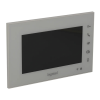
321070 7" Touch screen internal unit
323012 Softswitchbard for Laptop
L1 Electric door lock 12V - 4A impulsive
PB Door lock release pushbutton
system witH d45 interface and fiber optic connection
B
D
C
Laptop
WIRING DIAGRAMS
90
 Loading...